Stacked electrochemical cell

a technology of electrochemical cells and stacking, applied in the field of electrochemical elements, can solve the problems of battery flammability and explosives, lithium ion polymer batteries, and relatively low capacity of lithium ion polymer batteries, and achieve the effect of efficient use of space and easy manufactur

Inactive Publication Date: 2005-04-19
LG ENERGY SOLUTION LTD
View PDF17 Cites 29 Cited by
  • Summary
  • Abstract
  • Description
  • Claims
  • Application Information

AI Technical Summary

Benefits of technology

[0011]It is an objective of the present invention to provide an electrochemical element comprising electrochemical cells which are multiply stacked, wherein it is easy to manufacture, and has a structure making efficient use of the space available while considering the prior art.
[0012]It is another objective of the present invention to provide an electrochemical element that can maximize the content of the active electrode material.

Problems solved by technology

These lithium ion batteries, however, have safety problems resulting from the use of organic electrolyte, which causes the batteries to be flammable and explosive.
Also, lithium ion has the weakness of having difficult manufacturing process.
These lithium ion polymer batteries, however, have relatively low capacity compared to lithium ion batteries and have especially insufficient discharging capacity at low temperatures; and thus, need to be improved.
This structure, however, has small radius of curvature at the center portion of the spiral, which often results in extreme stresses at the bending surface of the electrode, often causing exfoliation of the electrode.
This facilitates the deposition of lithium metal at the center portion of the electrode during the repeated charge and discharge of the battery, which may shorten the lifespan of the battery while degrading the safety of the battery.
This method is not free from aforesaid problems of reduced lifespan and safety, but rather has increased problems caused by the decrease in the radius of curvature due to the oval shape.
Also, the problem of reduced performance is greater because manufacturing a tight spiral structure is inherently impossible.
Furthermore, discrepancy of the oval shape of the jelly role and the rectangular shape of the container reduces the rate of utilized volume.
These proposals, however, only provides partial solution to the problems or causes other problems more difficult to solve so that they have not become a practical solution.
The laminated cells were so stiff that it was difficult to fold and when it was folded by exerting force, the problem arose in the folded area because it was fractured in a manner similar to the jellyroll typed cells.
Thus, the problems of exfoliations, cracks, crumbles or snapping, encountered in jelly role type structure also occur frequently.
Also, the cells with this structure are inherently prone to snapping; and therefore, the possibility of making a practically applicable battery is very low.
But, there is difficulty in composing such a cell.
Furthermore, too much current collectors are used and the structure wastes too much electrolyte.
Thus, the structure is not very practical because it has many inefficient factors.

Method used


Image

  • Stacked electrochemical cell
  • Stacked electrochemical cell
  • Stacked electrochemical cell

Examples


example 1

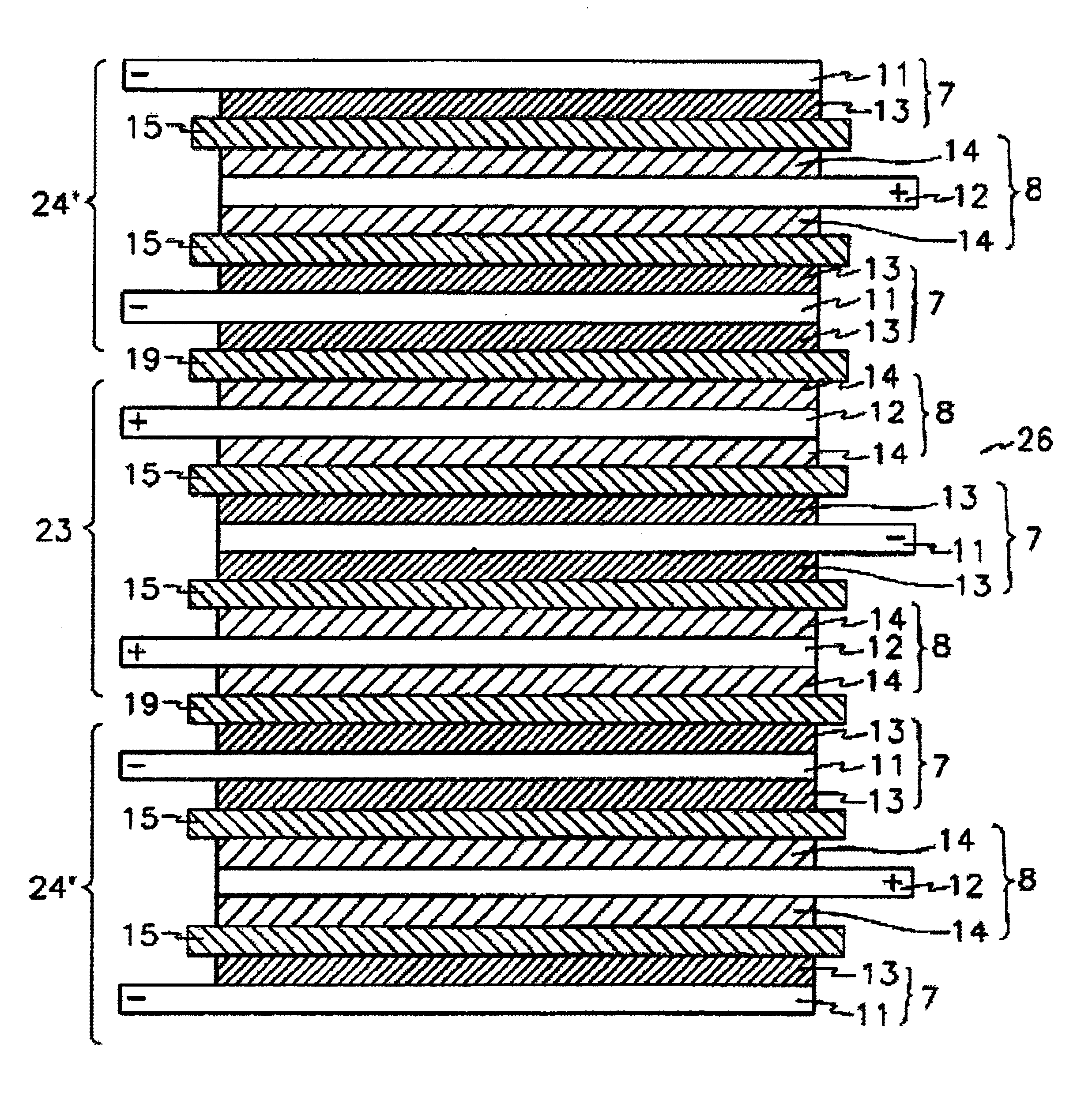
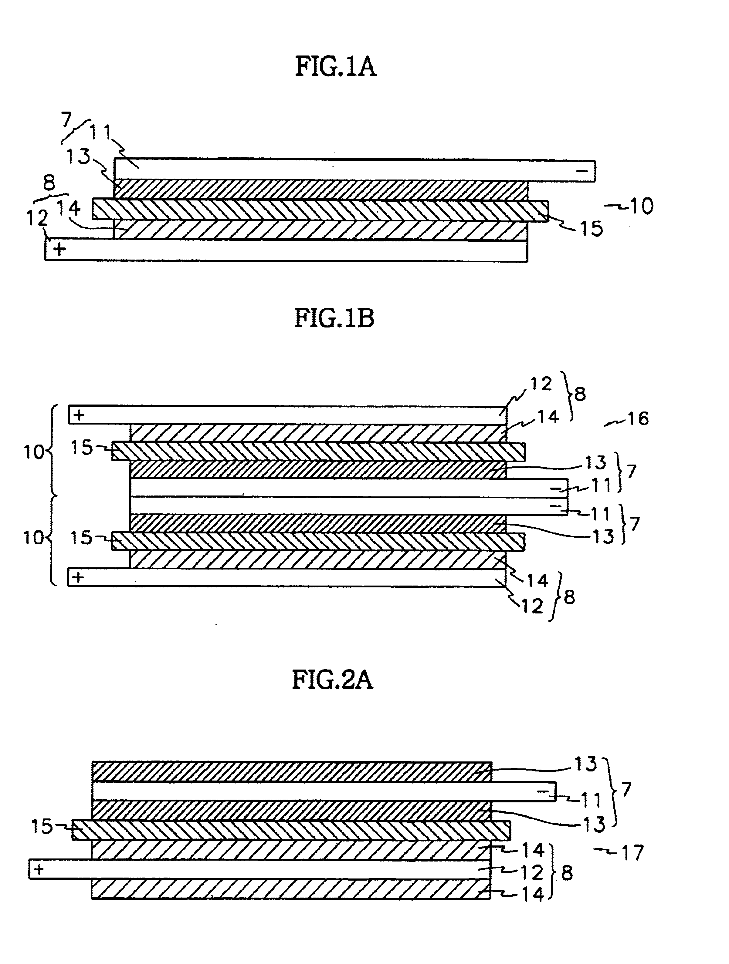
[0044]Preparing a Stacked Cell where a Full Cell is a Basic Unit

[0045](Preparing a Cathode)

[0046]LiCoO2:carbon black:PVDF, of which the weight ratio was 95:2.5:2.5, was dispersed in NMP in order to prepare slurry, and then the slurry was coated on an aluminum foil. After sufficiently drying at 130° C., the cathode was prepared by pressing.

[0047]A cathode that was to be placed in the outermost side of the outermost full cell was prepared by coating the slurry on a single side of aluminum foils. That is, the cathode has a cathodic material coated on a single side of the aluminum cathode current collector. A cathode of the full cell that was to be placed in the inner side was prepared by coating the slurry on both sides of aluminum foil. In this case, the cathode has a cathodic material coated on both sides of the aluminum cathode current collector. The thickness of the single-side coated cathode was 105 μm and the thickness of the both-side coated cathode was 140 μm.

[0048](Preparing a...

example 2

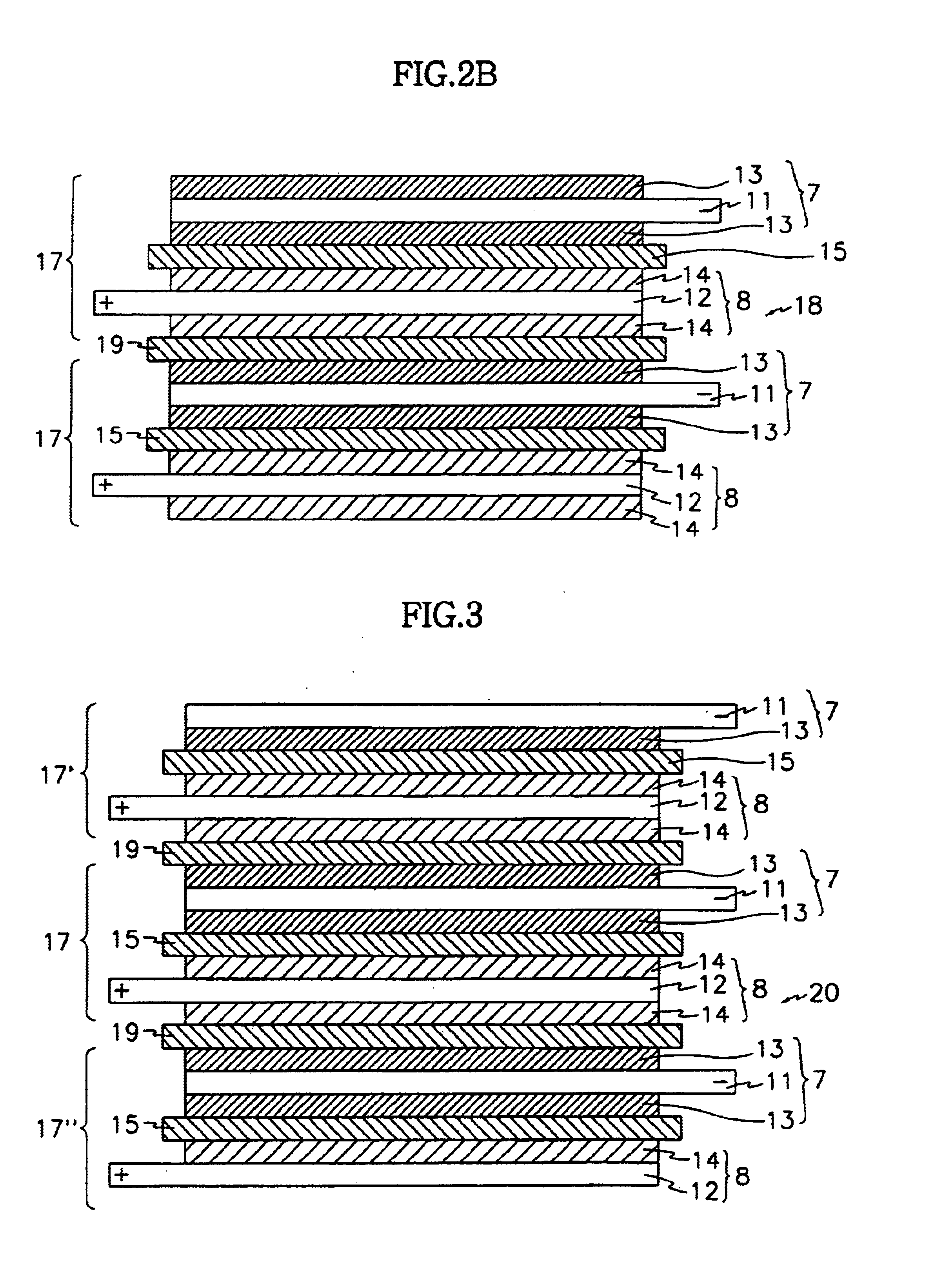
[0062]Preparing a Stacked Cell where a Bicell is a Basic Unit

[0063](Preparing a Cathode)

[0064]Each cathode was prepared according to the method same as the above example 1.

[0065]A cathode of the bicell that was to be placed in the inner side was prepared by coating the slurry on both sides of aluminum foil. That is, the cathode has a cathodic material coated on both sides of the aluminum cathode current collector. The thickness of the both-side coated cathode was 140 μm.

[0066](Preparing an Anode)

[0067]Each anode was prepared according to the method same as the above example 1.

[0068]Anodes that were to be placed in the outermost sides of the outermost full cell were prepared by coating the slurry on a single side and on both sides of copper foils. That is, the anodes have an anodic material coated on a single side and on both sides of the copper anode current collector respectively. An anode of the full cell that was to be placed in the inner side was prepared by coating the slurry o...


PUM

PropertyMeasurementUnit
thicknessaaaaaaaaaa
thicknessaaaaaaaaaa
thicknessaaaaaaaaaa

Abstract

An electrochemical element with improved energy density is provided. The electrochemical element has electrochemical cells which are multiply stacked. The electrochemical cell is stacked with the full cell or bicell as a basic unit and a separator film is interposed between the adjoining portion of the cells. The electrochemical element is easy to manufacture, has a structure which uses the space available efficiently, and can maximize the content of the active electrode material so that a highly integrated battery can be implemented.

Description

BACKGROUND OF THE INVENTION[0001](a) Field of the Invention[0002]The present invention relates to an electrochemical element, specifically an electrochemical element with improved energy density comprising multiply stacked electrochemical cells.[0003](b) Description of the Related Art[0004]There has been growing interest on energy storage technology. The applicable field of the battery has been expanded to cellular phones, camcorders and notebook computers with recent addition of electric vehicles into this list. Such expansion has led to increased research and development of batteries with visible outcomes. In this respect, researches on electrochemical elements are one of the fields that have been receiving much attention, among which rechargeable battery is the central field of interest. Recent developments have turned its way to designing new batteries and electrodes to improve capacity and specific energy.[0005]Among the secondary batteries being used, lithium ion battery devel...

Claims


Application Information

Patent Timeline
Patent Type & Authority Patents(United States)
IPC IPC(8): H01M10/38H01M10/40H01M10/36H01M6/46H01M10/04H01M6/42H01M2/16H01M6/04H01M6/10H01G9/025H01G9/26H01G11/08H01G11/10H01G11/12H01G11/14H01G11/22H01G11/52H01G11/56H01G11/66H01G11/70H01G11/72H01G11/84H01G11/86H01M10/05H01M10/0565H01M10/0585H01M50/417H01M50/42H01M50/426H01M50/457
CPCH01G9/26H01M2/1686H01M6/46H01M10/0565H01M10/0585H01M10/38H01M10/0436H01M2/1653H01M6/10Y02E60/13H01M10/0525Y02E60/10Y02P70/50H01M50/417H01M50/457H01M50/426H01M50/42H01M10/058
Inventor AHN, SOON-HOLEE, HYANG-MOKLEE, SEUNG-JINKIM, TAE-HYUNGLEE, HYUNG-KEUN
Owner LG ENERGY SOLUTION LTD
Why Eureka
Try Eureka