Filter assembly for exhaust gases

a technology for filter assembly and exhaust gases, applied in the direction of filtration separation, combustion-air/fuel-air treatment, separation process, etc., can solve the problems of reducing the overall performance and longevity of the turbocharger, affecting the performance and effectiveness of such bearings, and damage or degrad

Inactive Publication Date: 2005-04-26
BENDIX COMML VEHICLE SYST LLC
View PDF25 Cites 51 Cited by
  • Summary
  • Abstract
  • Description
  • Claims
  • Application Information

AI Technical Summary

Benefits of technology

[0008]Additionally, an exemplary embodiment includes a spring positioned directly beneath the filter unit for stabilizing the filter unit within the chamber and for urging the filter unit upward into sealing engagement with the inlet port. The spring also serves as a bypass system that allows air to pass directly from the inlet port to the outlet port if the filter element becomes clogged or plugged. An end cap positioned directly beneath the filter unit and directly on top of the spring further stabilizes the filter unit within the housing. The lower housing section also includes a ring, indentation, or groove for stabilizing the spring within the housing while upper housing section further includes a collar formed around the base of the air inlet port for stabilizing the filter unit within the housing. The lower housing section also includes a sump for collecting contaminants captured by the filter unit.

Problems solved by technology

The high temperatures generated by internal combustion engines cause this nitrogen to react with any unused oxygen and results in the formation of nitrogen oxides [NOX], which are considered to be one of the main environmental pollutants emitted by vehicle engines.
Such bearings typically include a polymeric surface coating that can be damaged or degraded by physical contact with oil or other hydrocarbons.
Degradation of this polymeric surface decreases the performance and effectiveness of such bearings and can reduce the overall performance and longevity of the turbocharger.
Thus, in vehicles that utilize both exhaust gas recirculation systems and turbochargers with oil-free bearings, the possibility exists that certain contaminants present in the re-circulated exhaust gases can damage the turbocharger's bearings.

Method used


Image

  • Filter assembly for exhaust gases
  • Filter assembly for exhaust gases
  • Filter assembly for exhaust gases

Examples


Embodiment Construction

Reference Numerals

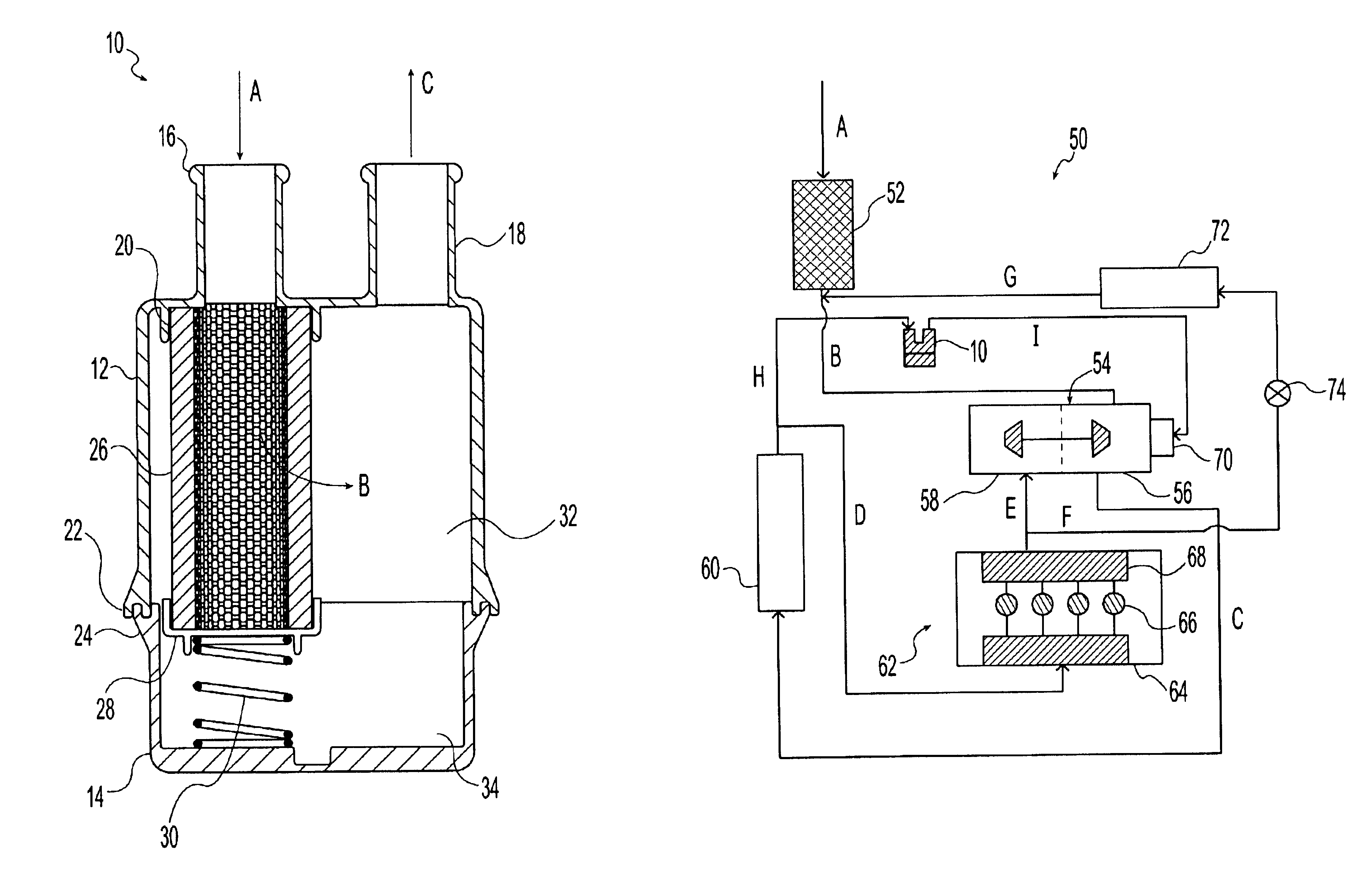
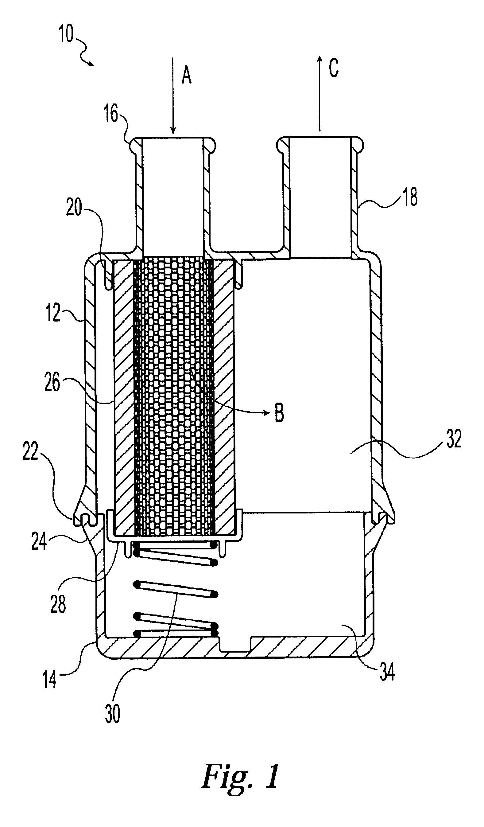
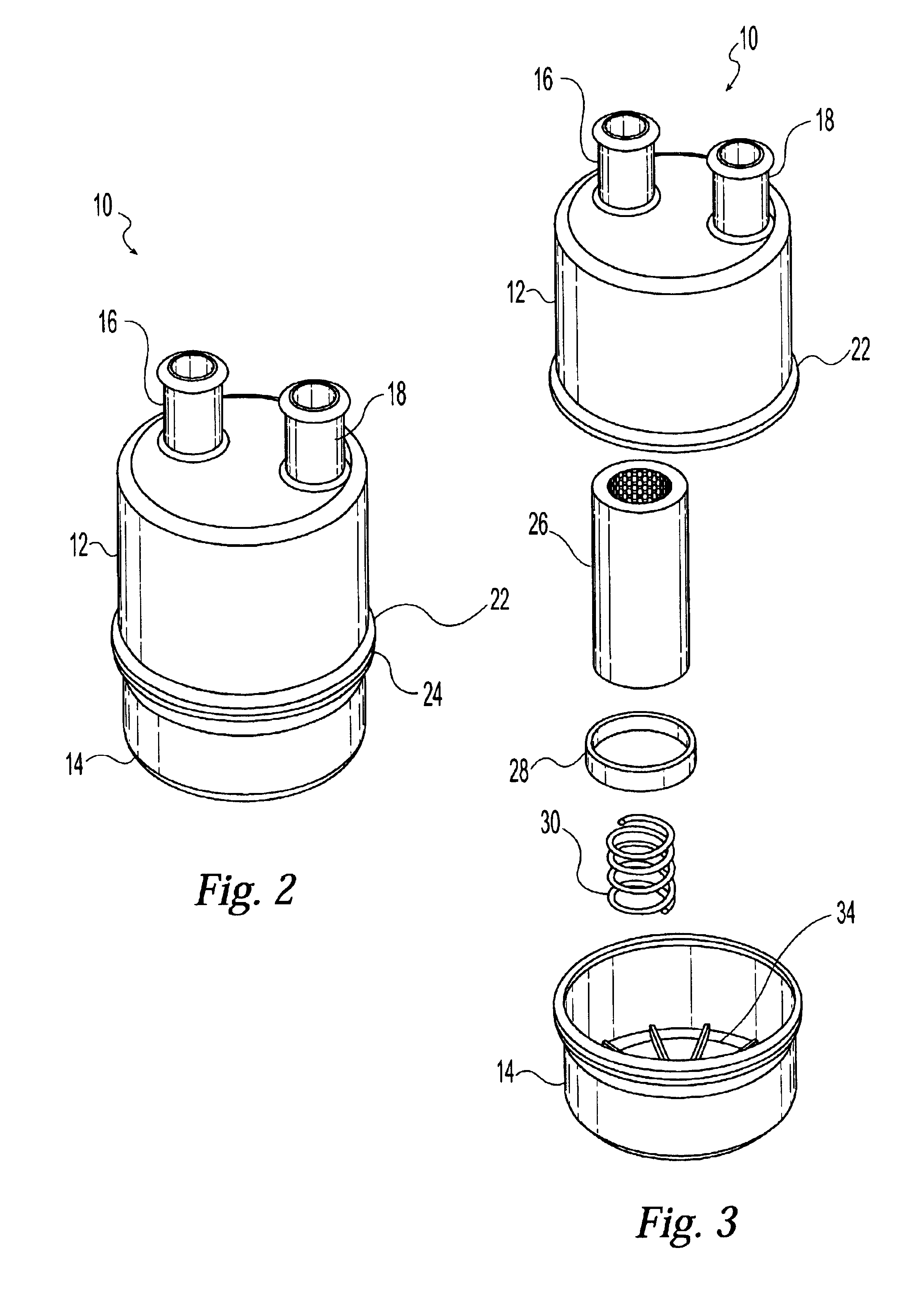
[0015]10 filter assembly[0016]12 upper housing section[0017]14 lower housing section[0018]16 inlet port[0019]18 outlet port[0020]20 collar[0021]22 first joining member[0022]24 second joining member[0023]26 filter unit[0024]28 end cap[0025]30 spring[0026]32 chamber[0027]34 sump[0028]50 engine system[0029]52 air filter[0030]54 turbocharger[0031]56 compressor[0032]58 turbine[0033]60 intercooler[0034]62 engine[0035]64 intake manifold[0036]66 combustion chambers[0037]68 exhaust manifold[0038]70 air bearing[0039]72 EGR cooler[0040]74 valve

[0041]With reference to FIGS. 1-3, and according to an exemplary embodiment of the present invention, filter assembly 10 includes a substantially cylindrical external housing, a filter unit 26, and an internal support mechanism. The external housing component further includes an upper housing section 12 and a lower housing section 14 which are detachably connected at and by first joining member 22 and second joining member 24. Filter un...


PUM

PropertyMeasurementUnit
physicalaaaaaaaaaa
temperaturesaaaaaaaaaa
combustion temperatureaaaaaaaaaa

Abstract

An in-line filter assembly for filtering engine exhaust gases utilized by turbocharged internal combustion engine systems. The filter assembly includes an external housing having a lower housing section and an upper housing section. The upper housing section further includes an air inlet port and an air outlet port. A filter unit for decontaminating the exhaust stream is positioned below the air inlet port. An interior chamber is in communication with the outlet port and surrounds the filter unit. A spring positioned directly beneath the filter unit stabilizes the filter unit within the chamber and urges the filter unit upward into sealing engagement with the inlet port. The lower housing section also includes a sump for collecting contaminants captured by the filter unit.

Description

TECHNICAL FIELD OF THE INVENTION[0001]The present invention relates in general to filtration devices for automotive applications, and more specifically to a filtration assembly for removing liquid and solid contaminants from exhaust gases in a turbocharged air stream that is used to cool the bearing of the turbocharger.BACKGROUND OF THE INVENTION[0002]An internal combustion engine requires oxygen for the fuel utilized by the engine to be effectively combusted. Oxygen is typically supplied to such engines by drawing ambient air from the external environment into the engine. While the air drawn into the engine provides the necessary oxygen, ambient air also contains a large quantity of nitrogen. The high temperatures generated by internal combustion engines cause this nitrogen to react with any unused oxygen and results in the formation of nitrogen oxides [NOX], which are considered to be one of the main environmental pollutants emitted by vehicle engines.[0003]Exhaust gas recirculati...

Claims


Application Information

Patent Timeline
Patent Type & Authority Patents(United States)
IPC IPC(8): F01N3/031F01N3/021F01N3/022F02B37/00
CPCF01N3/0214F01N3/0226F01N3/031Y02T10/20F01N2410/08F02B37/00F01N2330/102Y02T10/12
Inventor FORNOF, WILLIAM P.
Owner BENDIX COMML VEHICLE SYST LLC
Why Eureka
Try Eureka