Polymer electrolyte fuel cell

a fuel cell and electrolyte technology, applied in the field of polymer electrolyte fuel cells, can solve the problems of reducing the removal efficiency of generated water, deteriorating cell performance, and affecting cell performance, and achieve the effect of improving the conductive separator

Inactive Publication Date: 2005-04-26
PANASONIC CORP
View PDF12 Cites 62 Cited by
  • Summary
  • Abstract
  • Description
  • Claims
  • Application Information

AI Technical Summary

Benefits of technology

[0026]In view of the above, the present invention provides a polymer electrolyte

Problems solved by technology

However, supplying the highly humidified gases above the cell operating temperature causes condensation of water within the cell, so that the water drops disturb smooth supply of the gas; on the air electrode side to which the oxidant gas is supplied, water generation as a result of electric power generation lowers the removal efficiency of the generated water, thereby deteriorating the cell performance.
When a gas prepared by steam reforming a fossil fuel such as methanol or methane is used as the fuel gas, such humidification may be unnecessary in some cases since the reformed gas contains steam.
As described above, when the unevenness of the hydrogen and steam partial pressures in the fuel gas, the unevenness of the oxygen and steam partial pressures in the oxidant gas, the temperature distribution, etc., become excessive within the unit cell, the cell performance is greatly deteriorated due to excessive dryness or overdry, or excessive wetness or overflooding.
Further, a phenomenon of coexistence of the overdry and the overflooding within the unit cell occurs also due to the unevenness of the hydrogen and steam partial pressures in the fuel gas, the unevenness of the oxygen and steam partial pressures in the oxidant gas, the temperature distribution within the unit cell, etc., which are caused by the above-mentioned reasons.
In a stack of a large number of cells, occurrence of the above problem in a part of the cell stack may interfere with the operation of the whole cell stack.
Specifically, when a part of the cell stack becomes overflooded, the loss of gas supply pressure increases in the overflooded cell.
Since the manifolds for gas supply are shared in the cell stack, the gas does not flow smoothly into the overflooded cell, consequently increasing the overflooding.
On the other hand, when a part of the cell stack becomes overdried, the loss of gas supply pressure decreases in the overdried cell.
Thus, the gas flows smoothly into the overdried cell, consequently increasing the overdry.
The above-described problem often results from the fact that the steam partial pressure in the gas is higher on the gas outlet side than on the gas inlet side on both the fuel electrode side to which the fuel gas is supplied and the air electrode side to which the oxidant gas is supplied.
Further, when the conductive separator plate is composed of a carbon material, the process of forming a gas flow channel by cutting is costly; thus, an attempt has been made in which a carbon powder, carbon fiber or the like is mixed with a resin and is molded by a process such as hot

Method used


Image

  • Polymer electrolyte fuel cell
  • Polymer electrolyte fuel cell
  • Polymer electrolyte fuel cell

Examples


embodiment 1

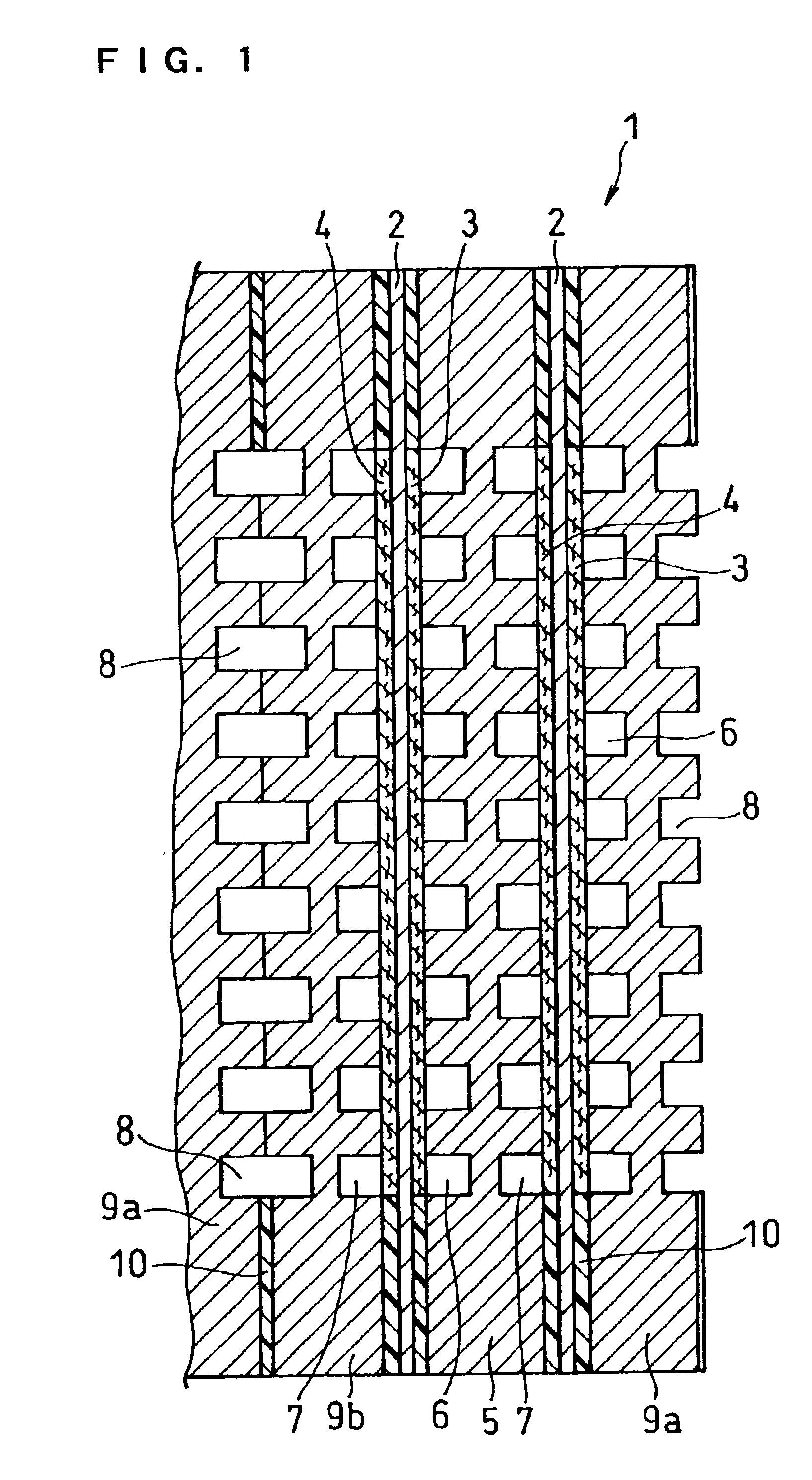
[0060]FIG. 1 is a cross sectional view illustrating the main part of a fuel cell in this embodiment.

[0061]A fuel cell 1 is composed of unit cells comprising a hydrogen-ion conductive polymer electrolyte membrane 2 and a cathode 3 and an anode 4 sandwiching the electrolyte membrane 2, the unit cells being stacked with a conductive separator plate interposed therebetween. The conductive separator plates inserted between the cells comprises: a single separator plate 5 having oxidant gas flow channels 6 on one side and fuel gas flow channels 7 on the other side and thus having both functions of a cathode-side separator plate and an anode-side separator plate; and a composite separator plate composed of a separator plate 9a having the oxidant gas flow channels 6 on one side and cooling water flow channels 8 on the other side and a separator plate 9b having the cooling water flow channels 8 on one side and the fuel gas flow channels 7 on the other side. In this embodiment, the composite s...

embodiment 2

[0069]The following will describe another preferred embodiment of the conductive separator plate.

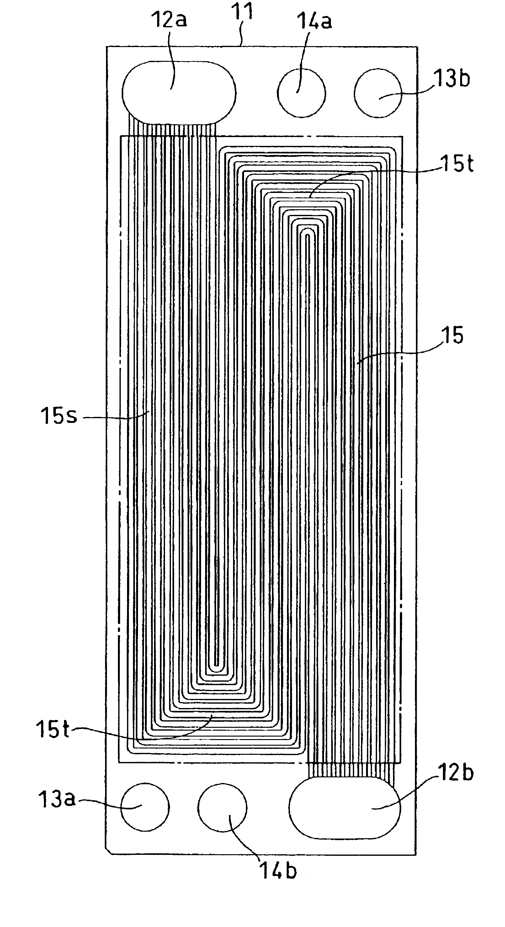
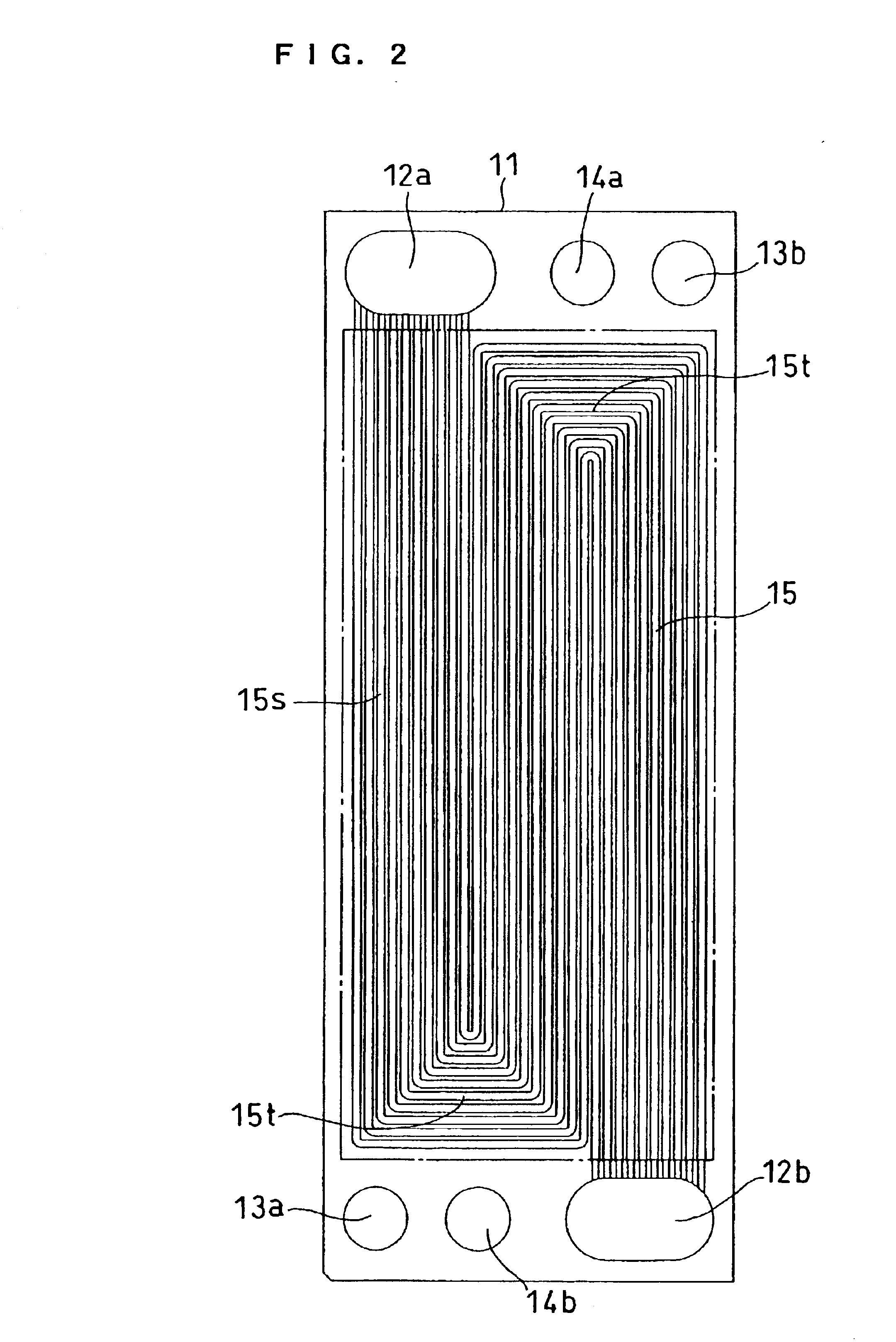
[0070]FIG. 5 is a front view of a cathode-side conductive separator plate. A separator plate 31 is a rectangle, wherein an oxidant gas inlet manifold 32a, a fuel gas inlet manifold 33a, and a cooling water inlet manifold 34a are arranged along one shorter side of the rectangle and an oxidant gas outlet manifold 32b, a fuel gas outlet manifold 33b, and a cooling water outlet manifold 34b are arranged along the other shorter side thereof. Gas flow channels 35 communicating with the oxidant gas inlet manifold 32a and the outlet manifold 32b are composed of 35 linear grooves.

[0071]FIG 6 is a front view of an anode-side conductive separator plate. A separator plate 41 is a rectangle, wherein an oxidant gas inlet manifold 42a, a fuel gas inlet manifold 43a, and a cooling water inlet manifold 44a are arranged along one shorter side of the rectangle and an oxidant gas outlet manifold 42b, a fuel...

embodiment 3

[0073]The following will describe another preferred embodiment of the cathode-side conductive separator plate with reference to FIGS. 7 to 9.

[0074]A separator plate 71 as shown in FIG. 7 has an oxidant gas inlet manifold 72a and an oxidant gas outlet manifold 72b along the shorter sides; in the vicinity of these manifolds along the longer sides, it has a fuel gas inlet manifold 73a, a fuel gas outlet manifold 73b, a cooling water inlet manifold 74a and a cooling water outlet manifold 74b. Gas flow channels 75 communicating with the oxidant gas inlet manifold 72a and the outlet manifold 72b are composed of linear grooves having a tapering width. Fuel gas flow channels and cooling water flow channels have a serpentine structure composed of liner parts and turns similar to FIG. 6.


PUM


Abstract

A polymer electrolyte fuel cell comprising a hydrogen-ion conductive polymer electrolyte membrane, an anode and a cathode sandwiching the hydrogen-ion conductive polymer electrolyte membrane, an anode-side conductive separator plate having gas flow channels for supplying a fuel gas to the anode, and a cathode-side conductive separator plate having gas flow channels for supplying an oxidant gas to the cathode, wherein the anode-side and cathode-side conductive separator plates have a substantially rectangular part in contact with the anode or cathode in which the length of a longer side is equal to or more than twice the length of a shorter side, and the oxidant gas flow channels have a linear part formed along the longer side of the rectangular part.

Description

TECHNICAL FIELD[0001]The present invention relates to a polymer electrolyte fuel cell of the room temperature operation type used for portable power sources, power sources for electric vehicles, domestic cogeneration systems, etc., and it particularly relates to improvements of conductive separator plates used therein.BACKGROUND ART[0002]A fuel cell comprising a polymer electrolyte generates electric power and heat simultaneously by electrochemically reacting a fuel gas containing hydrogen and an oxidant gas containing oxygen such as air. This fuel cell is basically composed of a pair of electrodes, i.e., an anode and a cathode, formed on both surfaces of a hydrogen-ion conductive polymer electrolyte membrane. The electrode usually comprises a catalyst layer which is composed mainly of carbon particles carrying a metal catalyst such as platinum group metal catalyst and a diffusion layer having both gas permeability and electronic conductivity formed on the outer surface of the catal...

Claims


Application Information

Patent Timeline
IPC IPC(8): H01M8/02H01M8/04H01M8/10H01M8/24
CPCH01M8/0247H01M8/0258H01M8/026H01M8/0263H01M8/04119H01M8/0267Y02E60/50H01M8/04156H01M8/1002H01M8/241H01M8/1007H01M8/2483H01M8/04H01M8/02
Inventor HATOH, KAZUHITONIIKURA, JUNJIOHARA, HIDEOKANBARA, TERUHISA
Owner PANASONIC CORP
Why Eureka
Try Eureka