Communications system for providing broadband communications using a medium voltage cable of a power system

a technology of broadband communication and power system, applied in the field of power line communications, can solve the problems of high frequency attenuation, high noise of overhead wires, and power lines that cannot readily transport signals

Inactive Publication Date: 2005-04-26
AMPERION
View PDF13 Cites 416 Cited by
  • Summary
  • Abstract
  • Description
  • Claims
  • Application Information

AI Technical Summary

Benefits of technology

[0032]Typically, the couplers are used to inject or extract the communications signal to or from the electrical power network. As is known in the art, there are two common types of couplers. Capacitive couplers use standard capacitive effects in order to link the two signals at high frequency, while isolating the data and power signals at 0 to 60 Hz. A capacitive coupler is electrically a capacitor, with one plate attached to the HV, MV, or LV conductor, and the other plate connected to the communications signal source or destination. Insulation between th...

Problems solved by technology

Because these loops produce a safety and fault detection and correction problem, they are typically opened in one place by an automatic switch or a manual Normally Open Point.
Such techniques are used because power lines do not readily transport signals above the 50 or 60 Hz for which they were designed.
Higher frequencies are attenuated quickly, and overhead wires particularly are very noisy, carrying radio and television signals, as well as other narrowband and broadband noise.
Any of these components may present barriers to propagation of the RF signals, and may require additional devices to create RF bridges around them.
It appears very likely that some network stations will not be able to “hear” other stations in the network because of the attenuation of RF signals over a large distance between stations, or the RF barriers along the power line.
This last point implies that a peer-to-peer network architecture is not appropriate for this system.
The power line environment, especially when using over...

Method used


Image

  • Communications system for providing broadband communications using a medium voltage cable of a power system
  • Communications system for providing broadband communications using a medium voltage cable of a power system
  • Communications system for providing broadband communications using a medium voltage cable of a power system

Examples


Embodiment Construction

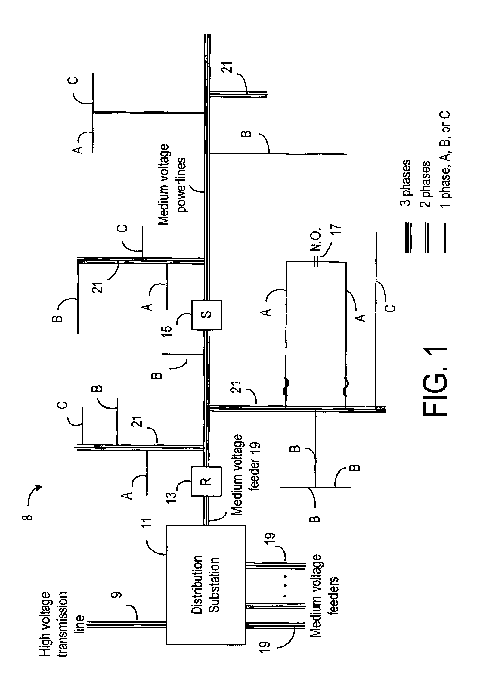
[0079]FIG. 1 illustrates the physical topology of a typical power distribution network 8. Incoming high voltage power is provided over high voltage transmission lines 9. A distribution power substation 11 receives this high voltage power and converts it to medium voltage, (typically 4 to 50 kV) power. This medium voltage (MV) power is distributed on MV feeders 19. A typical feeder may have multiple branches (called “laterals”21) as shown in FIG. 1. These feeders can extend for many kilometers, such as 25 kilometers (15.54 miles).

[0080]FIG. 1 also shows that a typical MV feeder includes various automatic switch gear, such as reclosers (R) 13, sectionalizers (S) 15, and disconnect elements 17. As is known in the art, reclosers act like circuit breakers so as to protect feeders from overload. Sectionalizers 15 and disconnect elements 17 are switches which are typically used to isolate a faulty section of a feeder and to re-route the feeder line path. A typical disconnect element 17 can...


PUM


Abstract

A broadband service communication system using an MV cable for conveying RF signals in a network segment, which includes a distribution center (PLT controller) and a plurality of power line telecommunication (PLT) stations. The PLT controller has a distribution modem for conveying downstream and upstream RF signals to and from the PLT stations through the MV cable via couplers. Each PLT station has a modem for conveying the downstream and upstream RF signals via couplers and for conveying media signals to one or more customer premises equipment (CPE) via, e.g. wireless links. The PLT controller controls each PLT station regarding upstream communications transfer of all downstream communications and also controls. The PLT controller can be connected via a router to a WAN to convey media signals to and from the WAN. Repeaters and interlinks are used to join multiple network segments.

Description

[0001]This patent application is based on and claims priority under 35 U.S.C. §119(e) to U.S. Provisional Application No. 60 / 383,838, filed May 28, 2002.FIELD OF THE INVENTION[0002]The present invention relates to power line communications (PLC), namely, the providing of broadband communications services using one or more medium voltage cables of a power distribution network, while the power distribution network is supplying electrical power generated by a power generation system.BACKGROUND OF THE INVENTIONOverview[0003]The present invention relates to communications services using the power distribution network. The following provides a general background of a power generation system used to supply power to the power distribution network, general background of a power transmission system, a power transmission system, a power distribution network, as well as background information concerning power line communications; that is, the use of the power distribution network to deliver inf...

Claims


Application Information

Patent Timeline
IPC IPC(8): H04L12/56H04Q7/20H04L12/28H04B3/54
CPCH04B3/54H04B3/542H04B3/58H04B2203/5441H04L27/2601H04B2203/5466H04B2203/5479H04L5/0007H04B2203/5445
Inventor HUNT, PHILIP G.RILEY, PAUL M.KOPP, LOWELL E.
Owner AMPERION
Why Eureka
Try Eureka