Object oriented microfluidic design method and system

Active Publication Date: 2005-04-26
STANDARD BIOTOOLS INC
View PDF15 Cites 211 Cited by
  • Summary
  • Abstract
  • Description
  • Claims
  • Application Information

AI Technical Summary

Benefits of technology

[0027]An advantage of the present invention is the reduction in time needed to complete the design and implementation of a microfluidic circuit. For example, in one embodiment of the present invention, synthesis, schematic capture, and functional simulation allow an efficient and expedient process of creating and validating an initial design, the physical layout tool allows easy placement and routing of multilayered components on a predefined template, the physical simulation allows the reduction in errors before fabrication, and the die placement tool allows faster wafer mask generation. The uses and results generated by the present invention include cell based assays (incl

Problems solved by technology

Because different protocols require different configurations, the design and manufacturing of such microfluidic systems can be time-consum

Method used


Image

  • Object oriented microfluidic design method and system
  • Object oriented microfluidic design method and system
  • Object oriented microfluidic design method and system

Examples


Embodiment Construction

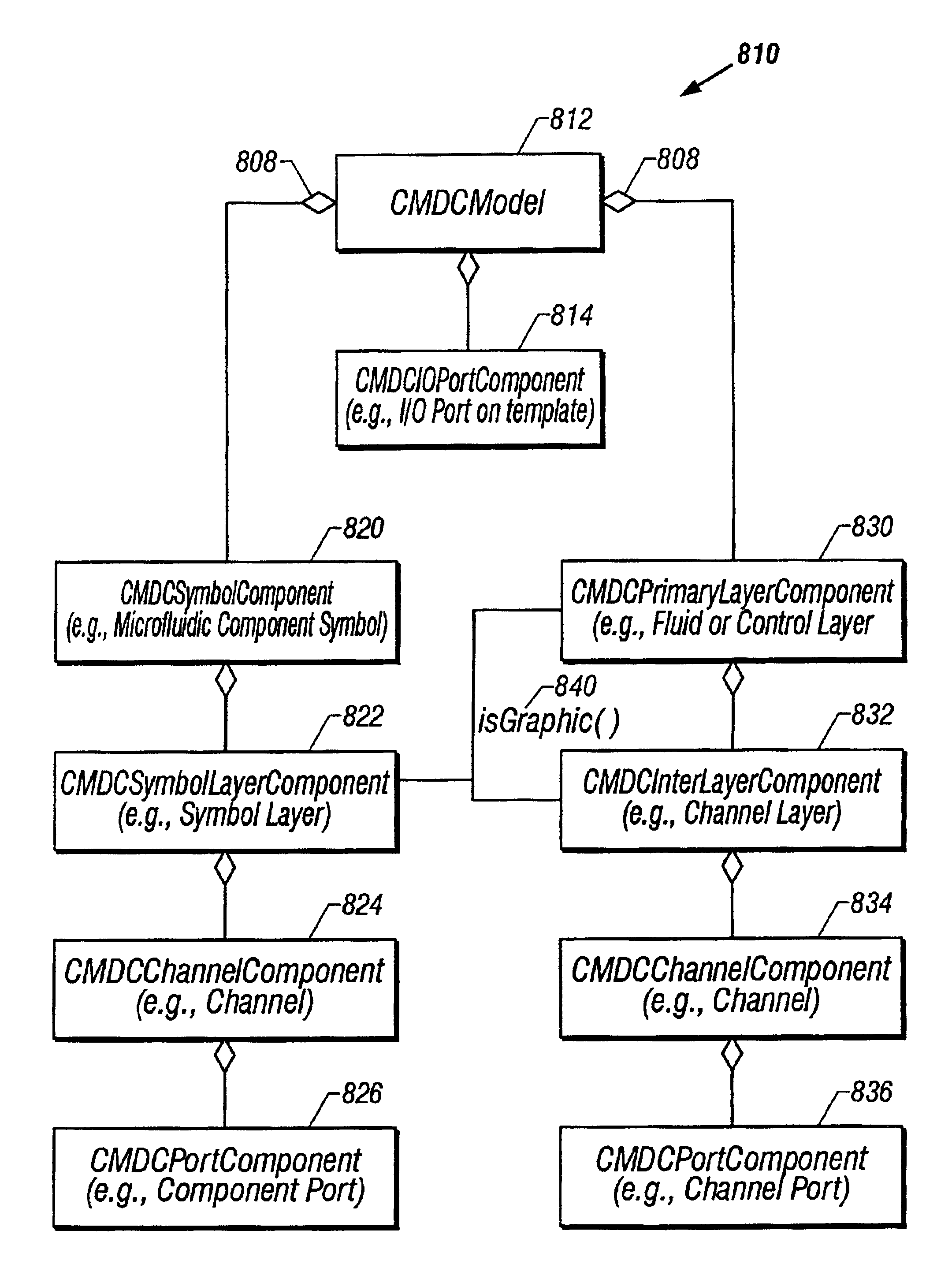
[0064]Embodiments of the present invention are directed to the design of customized microfluidic systems using a microfluidic computer aided design (MCAD) system. The MCAD system provides the user with the tools to design, analyze, and implement a customized microfluidic system using a plurality of building block microfluidic components.

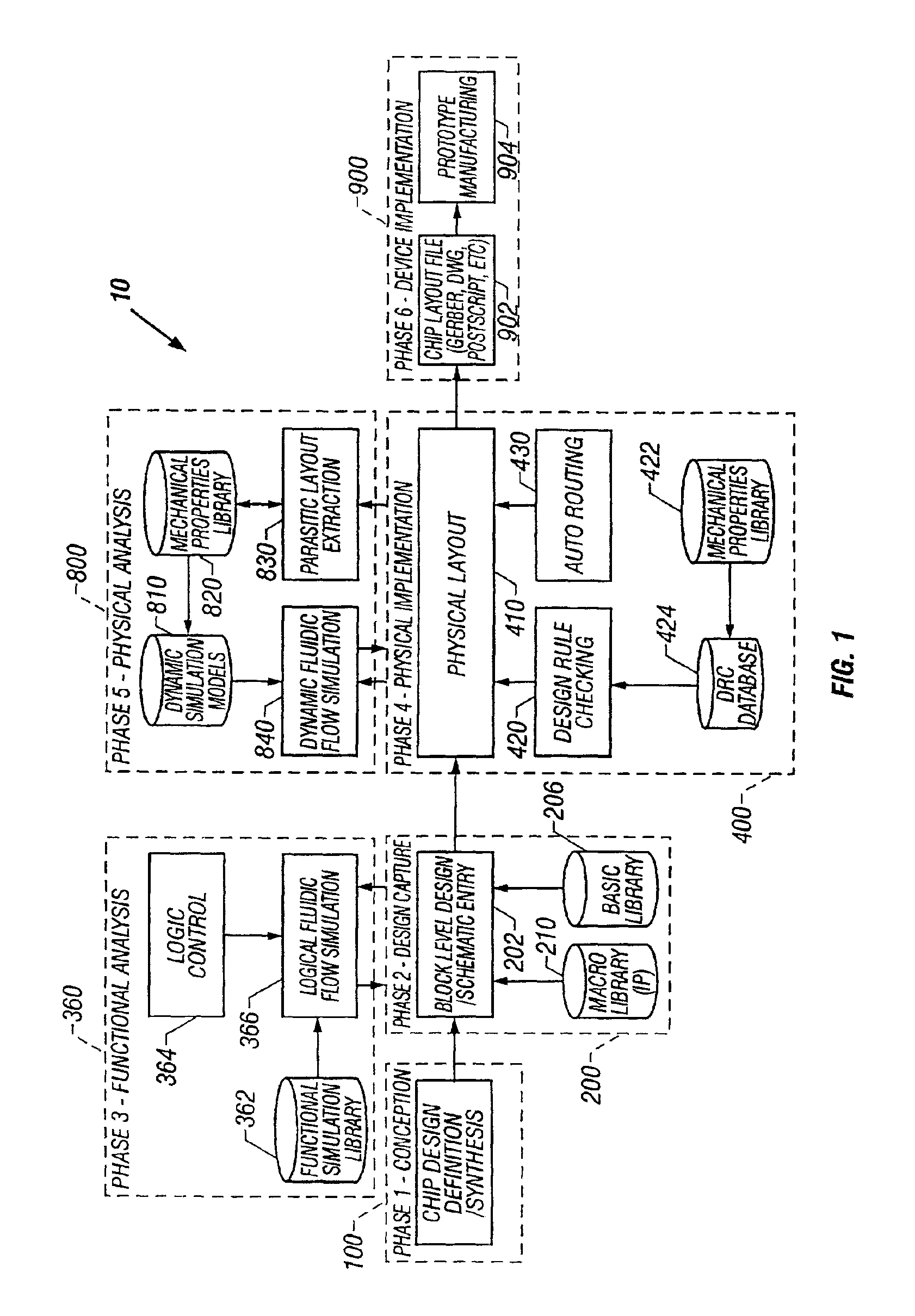
[0065]In one embodiment of the invention, the MCAD system includes a design capture module including a schematic entry tool for selecting and connecting microfluidic components according to a design. The system further includes a functional analysis module for functionally simulating selected microfluidic components of the design, a physical implementation module for arranging the microfluidic components into a physical layout according to the design, and a physical analysis module for physically simulating the microfluidic components in the physical layout.

[0066]In some embodiments, the modules comprise computer instructions or code stored in a comp...


PUM


Abstract

The present invention provides for the design of a microfluidic system, including a microfluidic chip or circuit, using an object oriented microfluidic computer aided design system. In an embodiment of the present invention, in a computer system having a computer memory and an object-oriented environment, a method for physically laying out a microfluidic circuit, having a plurality of microfluidic components is provided. First, a first symbol object representing a microfluidic component is placed, where the first symbol object includes a fluid channel object which represents a first fluid channel of the microfluidic component. Next, a connecting fluid channel object on a channel layer is placed, where the connecting fluid channel object represents a second fluid channel used to connect two microfluidic components of the plurality of microfluidic components. The fluid channel object is then linked to the connecting fluid channel object, where the linking represents connecting the first fluid channel to the second fluid channel.

Description

CROSS-REFERENCES TO RELATED APPLICATIONS[0001]This application claims priority from and incorporates by reference in its entirety U.S. Provisional Patent Application No. 60 / 214,595, titled “Biological Design Automation System,” by Michael Lee, et. al., filed Jun. 27, 2000.[0002]The following concurrently filed, commonly owned, patent applications are incorporated herein by reference in their entirety:[0003]U.S. patent application Ser. No. 09 / 894,857, entitled “A Microfluidic Design Automation Method And System,” by Michael Lee, et. al.[0004]U.S. patent application Ser. No. 09 / 894,862, entitled “A Computer Aided design Method and System For Developing A Microfluidic System,” by Michael Lee, et. al.,.[0005]The following references are incorporated herein by reference each in its entirety:[0006]PCT Patent Application No. PCT / US00 / 17740, entitled “Microfabricated Elastomeric Valve and Pump Systems,” filed Jun. 27, 2000 (U.S. patent application Ser. No. 09 / 605,520);[0007]PCT Patent Appli...

Claims


Application Information

Patent Timeline
IPC IPC(8): B01L3/00F15C5/00G06F17/50F16K99/00
CPCB01L3/502707F16K99/0001F16K99/0059G06F17/509Y10S707/99943B01L2200/12B01L2200/14B01L2300/123B01L2400/0487B01L2400/0638B01L2400/0655F16K2099/008F16K2099/0082G06F2217/16H01H2029/008B01L2200/0621G06F30/18G06F2111/10
Inventor HARRIS, GREGORYMONTGOMERY, JAMESLEE, MICHAELWORTHINGTON, GAJUS
Owner STANDARD BIOTOOLS INC
Why Eureka
Try Eureka