Turbo/drag pump having a composite skirt

Inactive Publication Date: 2005-05-03
ALCATEL LUCENT SAS
View PDF14 Cites 19 Cited by
  • Summary
  • Abstract
  • Description
  • Claims
  • Application Information

AI Technical Summary

Benefits of technology

[0013]The problem posed by the present invention is to devise a novel rotor structure for turbo/drag pumps making it possible, without risk of rotor dama

Problems solved by technology

With such a high speed of rotation, the rotor acquires very high kinetic energy, and is subjected to high mechanical stresses which require suitable materials to be selected.
Its shape is too complex to enable it to be made economically out of composite material.
At present, the pumping performance of turbo/drag pumps at high speeds of rotation is limited by the fact that it is not possible to increase the diameter of the Holweck skirt beyond a maximum limit.
However such an increase turns out to be impossible to achieve while using conventional materials, in particular metals, or even composite materials based on a metal matrix and containing reinforcing additives such as ceramics, powders, or fibers of carbon or other reinforcing materials.
However, a difficulty then lies in the differences between the mechanical and thermal properties of the o

Method used


Image

  • Turbo/drag pump having a composite skirt
  • Turbo/drag pump having a composite skirt
  • Turbo/drag pump having a composite skirt

Examples


first embodiment

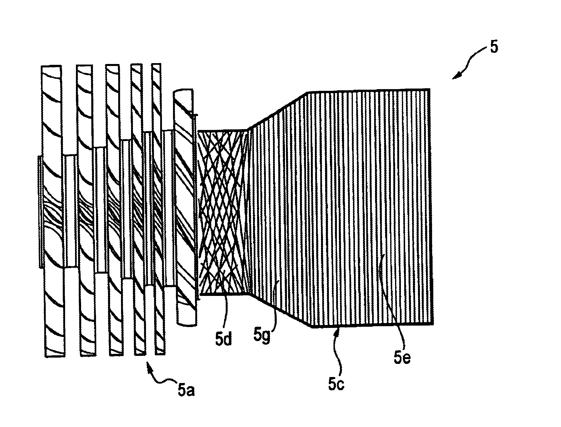
[0057]FIG. 4 shows a rotor 5 of the present invention.

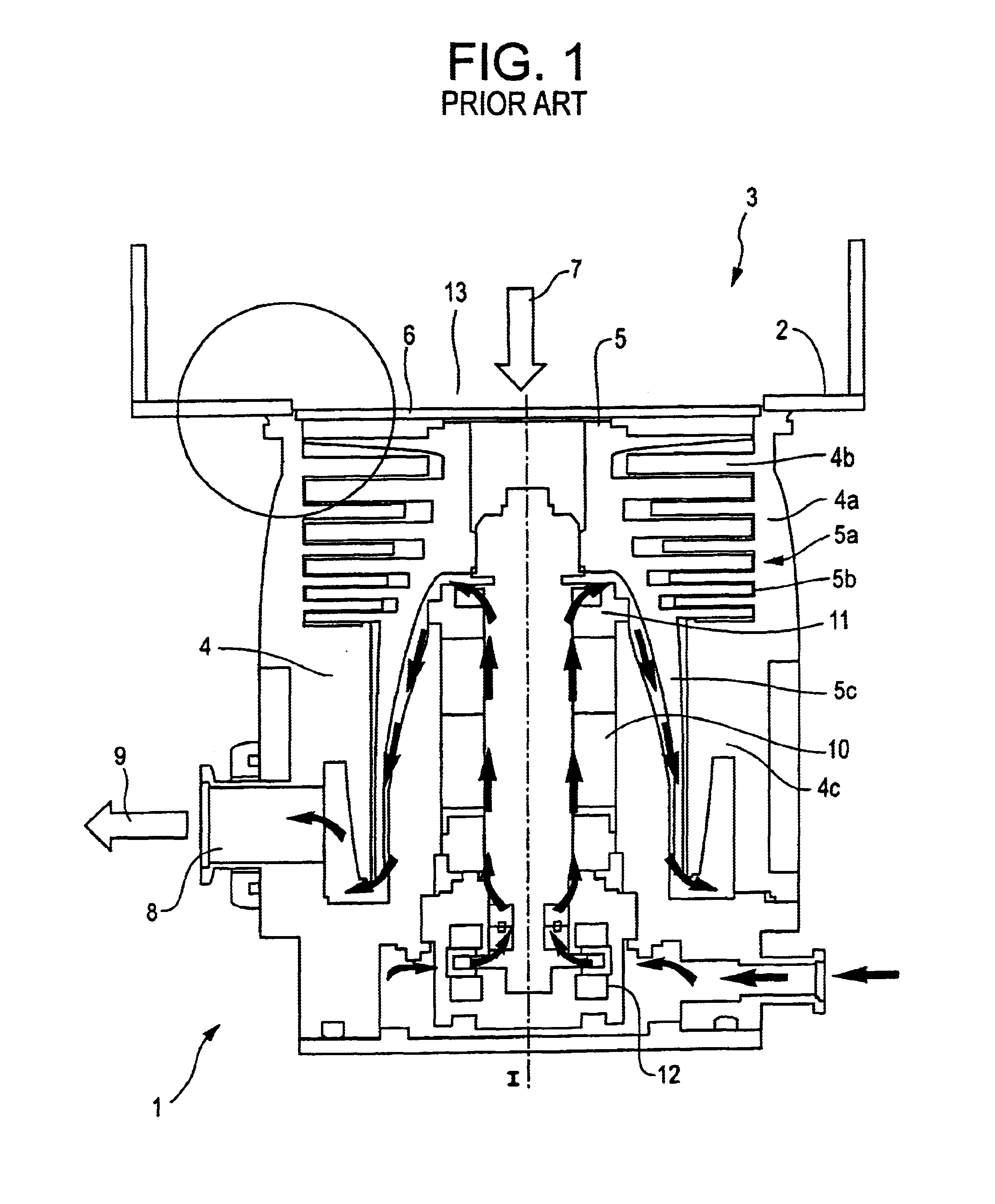
[0058]In this embodiment, the rotor 5 comprises the upstream rotor segment 5a made of metal with blades such as the blade 5b, and comprises the downstream rotor segment 5c in the form of a Holweck type tubular cylindrical skirt.

[0059]The annular connection region 5d and a transition region 5g adjacent thereto have internal reinforcing structures such that their mechanical and thermal characteristics are close to those of the metal or alloy constituting the upstream rotor segment 5a. For this purpose, the reinforcing structure comprises long fibers wound helically at a relatively large pitch, the fibers making an angle greater than 0° relative to the transverse plane, for example making an angle of 5° to 20° depending on the looked-for mechanical properties. In the downstream skirt region 5e, the long fibers are wound helically with an angle close to 0°, forming touching turns, thereby significantly improving the mechanical streng...

second embodiment

[0061]In this second embodiment, the annular connection region 5d has reinforcing fibers at a non-zero angle relative to the transverse plane, while the downstream skirt segment 5e, and possibly also the intermediate transition region 5g, have touching fibers making an angle close to 0° with the transverse plane.

[0062]Because of the reinforcement provided by the fibers at a zero angle, the cylindrical downstream skirt segment 5e can have a diameter that is significantly increased, thereby increasing the tangential speed of the skirt relative to the stator for given angular speed of rotation of the rotor, thus making it possible to increase the number of grooves 4d in the Holweck stator segment 4c (FIG. 6).

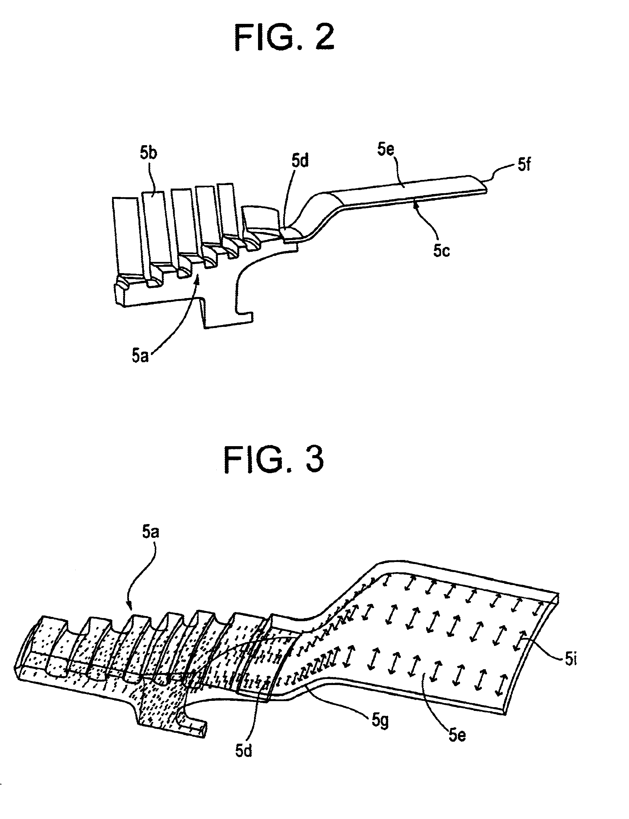
[0063]The advantage of this composite skirt structure is explained with reference to FIG. 3. This figure shows the mechanical stresses to which the rotor is subjected during high-speed rotation of the rotor: in the annular connection region 5d, the stresses are relatively small, wh...


PUM

PropertyMeasurementUnit
Angleaaaaaaaaaa
Fractionaaaaaaaaaa
Diameteraaaaaaaaaa

Abstract

There is provided a rotor for a turbo/drag vacuum pump, the rotor comprising an upstream rotor segment of the turbine type made of metal or alloy, and a downstream rotor segment of Holweck type made of composite material. The downstream segment of the rotor has a reinforcing structure made of long fibers that are distributed in a manner that varies as a function of the section under consideration: in the annular connection region connected to the upstream segment of the rotor, the fibers are inclined and/or spaced apart in order to conserve sufficient flexibility for the composite material to enable it to deform so as to track deformation of the metal of the upstream rotor segment while it is in operation; in contrast, the fibers are close together and form turns that touch in the downstream region of the skirt, thereby guaranteeing greater stiffness in order to withstand the mechanical stresses that occur during high-speed rotation of the rotor in operation. It is thus possible to make a rotor with a Holweck type skirt that is of greater diameter, thereby improving the properties of the pump.

Description

[0001]The present invention relates to vacuum pumps that rotate at high speed to generate a high vacuum in a vacuum pipe and / or a vacuum enclosure.BACKGROUND OF THE INVENTION[0002]In the electronic or micromechanical components industries, machining or plasma treatment processes are used that are performed in an enclosure where it is necessary to maintain a controlled vacuum atmosphere.[0003]Generating a vacuum requires pumps to be used that are capable of generating quickly a high vacuum that is suitable for the machining or treatment process, and that are capable of maintaining it. In general, turbo / drag type pumps are used, comprising a pump body in which a rotor is caused to rotate rapidly, for example rotation at more than 30,000 revolutions per minute (rpm).[0004]With such a high speed of rotation, the rotor acquires very high kinetic energy, and is subjected to high mechanical stresses which require suitable materials to be selected.[0005]The rotor of a turbo / drag vacuum pump...

Claims


Application Information

Patent Timeline
IPC IPC(8): F04D29/02F04D29/00F04D19/00F04D19/04F04D25/16
CPCF04D29/023F04D19/046F04D19/042F04D19/044F05D2300/43F05D2300/603F05D2300/10
Inventor FAVRE-FELIX, LIONELDAUVILLIER, OLIVIERBOUILLE, ANDRE
Owner ALCATEL LUCENT SAS
Why Eureka
Try Eureka