Gas turbine blade

a technology of gas turbine blades and blades, applied in the direction of magnetic recording, liquid fuel engine components, record information storage, etc., can solve the problem that magnesium oxide is not suitable for ceramic thermal insulation layers, and achieve the effect of small porosity

Inactive Publication Date: 2005-05-03
SIEMENS AG
View PDF12 Cites 12 Cited by
  • Summary
  • Abstract
  • Description
  • Claims
  • Application Information

AI Technical Summary

Benefits of technology

[0011]C) The thermal insulation layer also contains at least one oxide from the calcium oxide, silicon oxide, zirconium oxide and iron oxide group. As additives, these materials have a favorable effect on the material properties of the material.
[0015]G) The first and second layers preferably consist of 10 to 95 percent by weight magnesium aluminate (MgAl2O4) and 5 to 90 percent by weight magnesium oxide (MgO) as well as 0 to 20 percent by weight aluminum oxide (Al2O3), whereby the first layer has a smaller porosity than the second layer. The required porosity can then also particularly be obtained by the second layer lying on the outside whereas there is a more impervious structure in the first layer that, with regard to corrosive attacks, shields the hot gas more effectively against the metallic basic body lying beneath it.
[0016]H) The ceramic thermal insulation layer is preferably applied to a ceramic basic layer that has a porosity of less than 2 percent by volume. The ceramic basic layer can have the same chemical composition as the ceramic thermal insulation layer, but is sometimes also applied virtually completely imperviously to the metallic basic body. Therefore, the known porosity of the ceramic thermal insulation layer does not refer to this ceramic base layer. On the one hand, this again leads to a particularly favorable combination of good thermal insulation properties and, on the other hand, shields against corrosive attacks.

Problems solved by technology

It was previously assumed that, under high temperatures during thermal spraying, the magnesium oxide was not suitable for a ceramic thermal insulation layer.
However, because such impervious, non-porous structures, as mentioned above, are not suitable for a gas turbine blade application, this material was not taken into consideration as a ceramic thermal insulation layer on a gas turbine blade.

Method used


Image

  • Gas turbine blade
  • Gas turbine blade
  • Gas turbine blade

Examples


Embodiment Construction

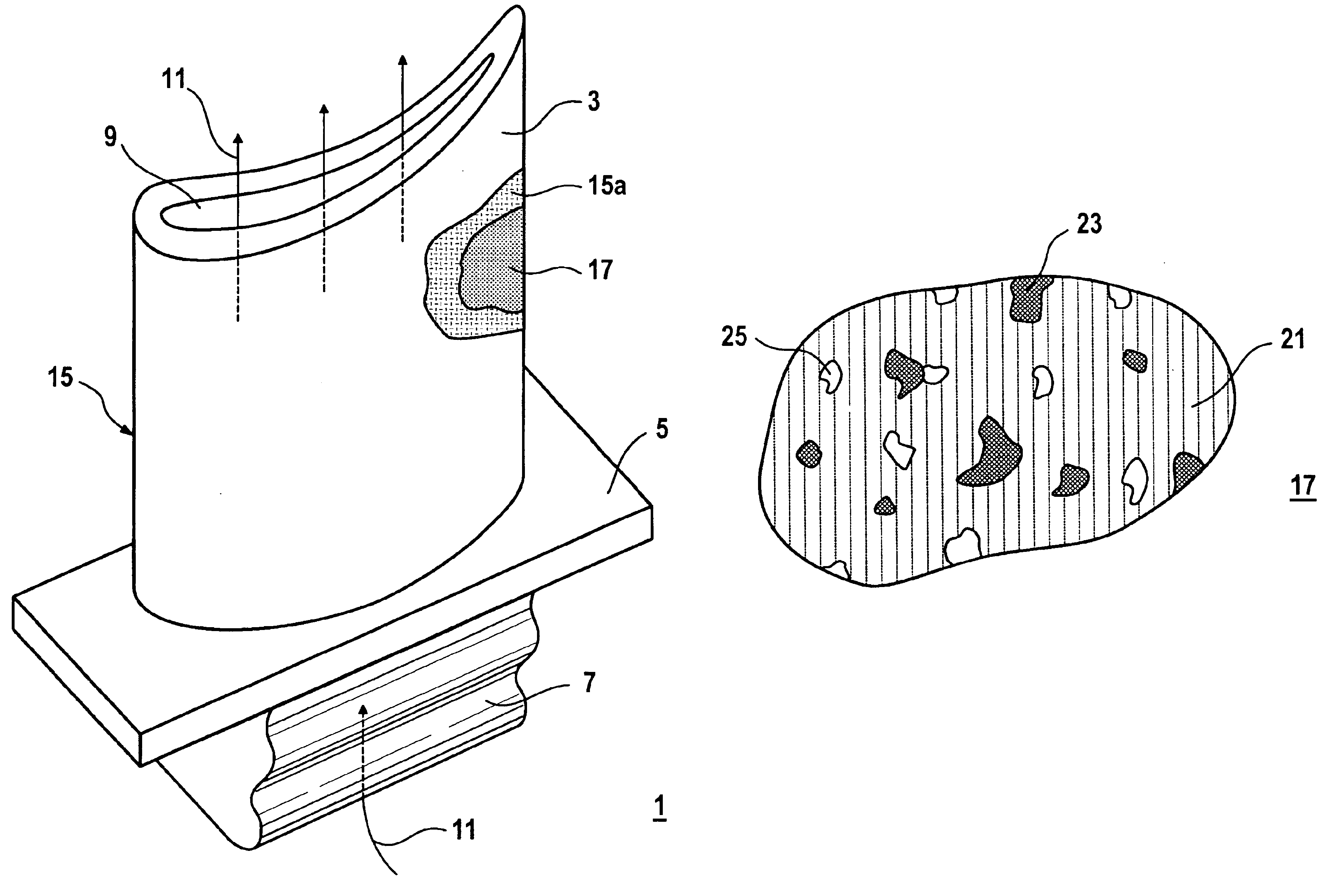
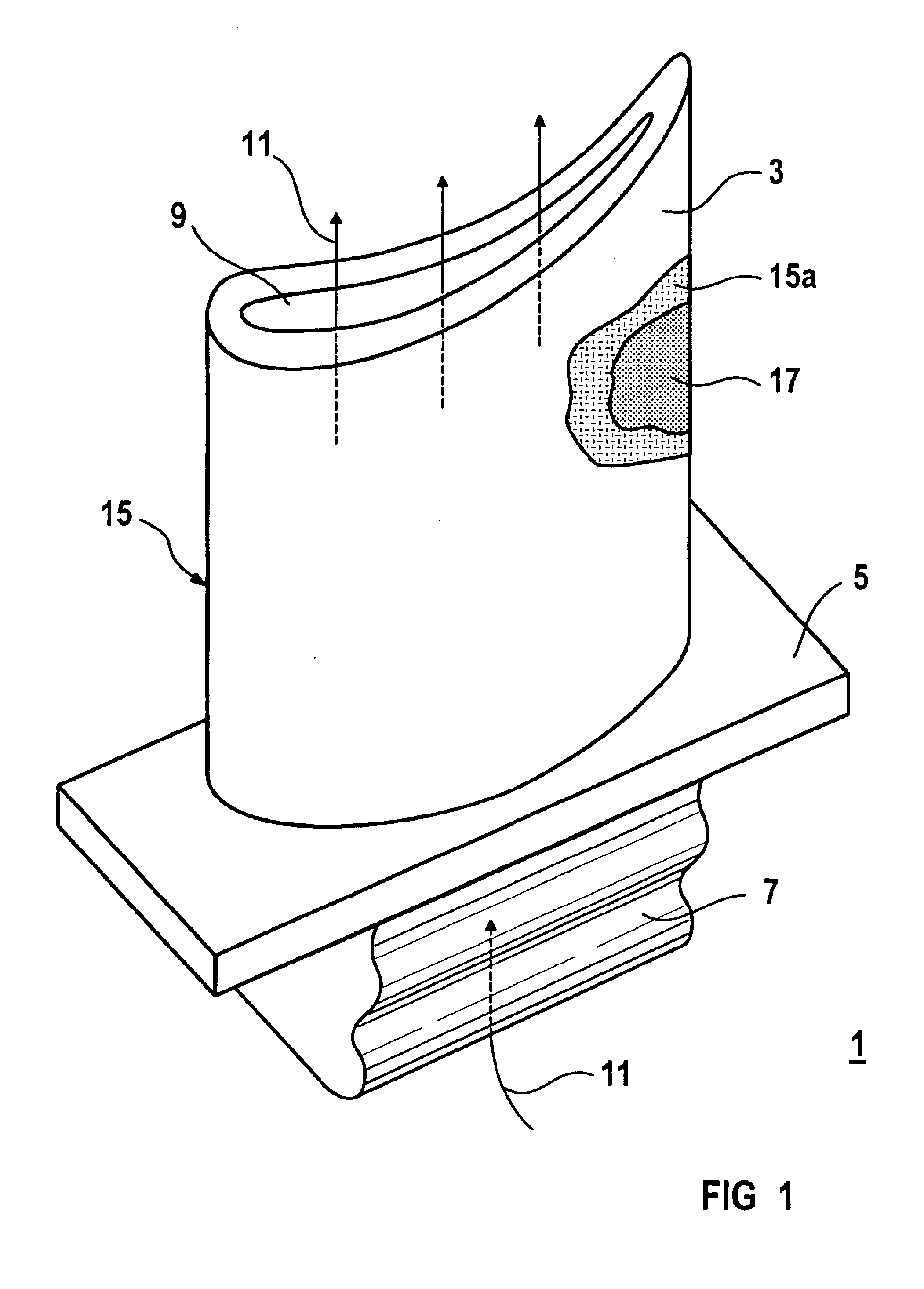
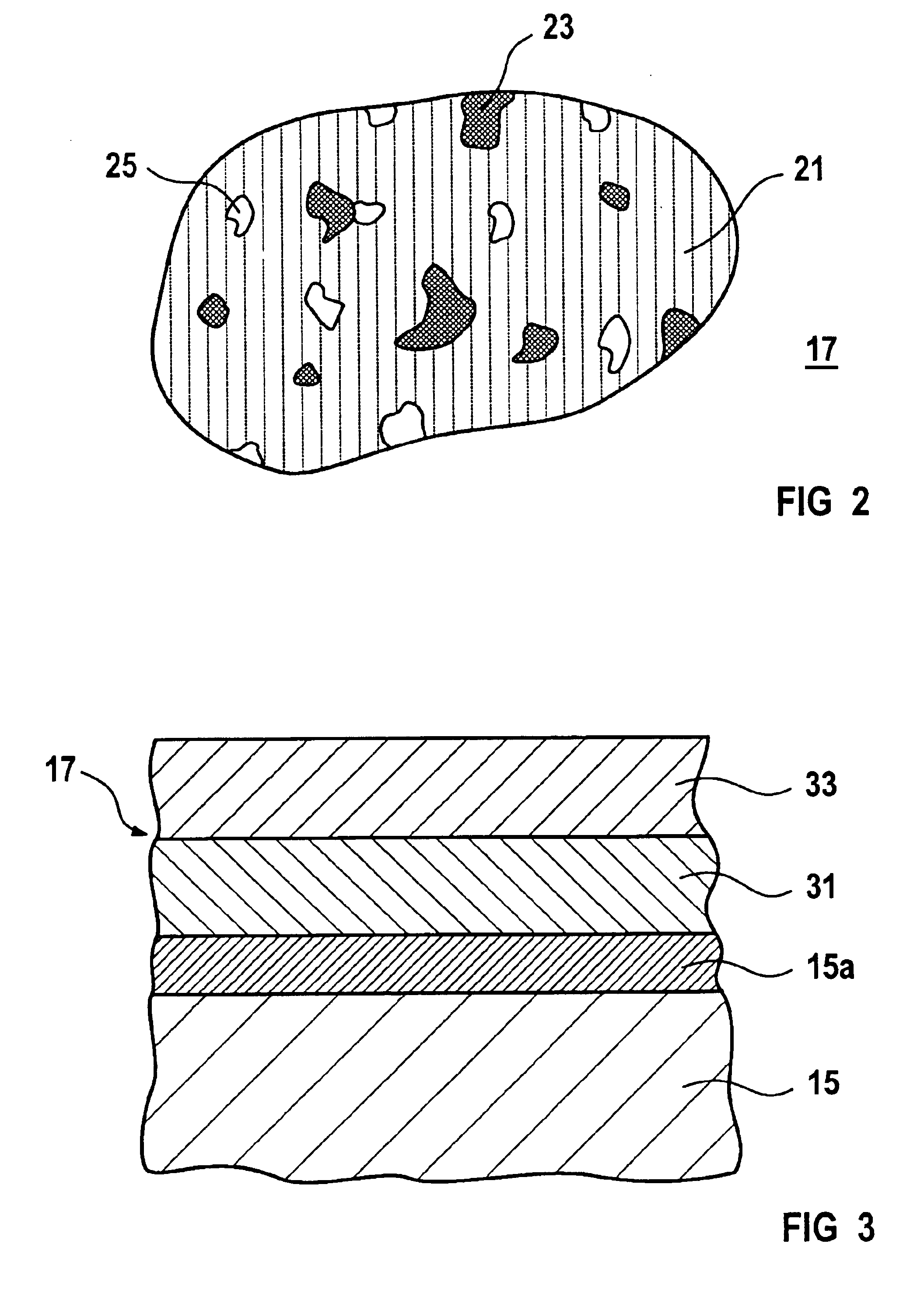
[0026]FIG. 1 shows a gas turbine blade 1. The gas turbine blade 1 has a blade 3, a platform 5 and a blade foot 7. The gas turbine blade 1 also has an inner cavity 9 through which cooling air 11 is fed for cooling. The gas turbine blade 1 is made up of a basic body 15 that consists of a nickel or cobalt base superalloy. The basic body 15 also includes an outer metallic corrosion protective layer 15A that provides both corrosion protection and bonds with the ceramic thermal insulation layer. Such a ceramic thermal insulation layer 17 is applied to the corrosion protective layer 15A.

[0027]When using the gas turbine blade 1, a very hot gas flows around blade 3. It is technically necessary to intensively cool the gas turbine blade 1 with cooling air 11. In addition, the ceramic thermal insulation layer 17 must thermally shield the gas turbine blade 1 from the hot gas. The platform 5 is used to shield the hot gas from a rotor disk not shown in greater detail. The blade foot 7 also engages...


PUM

PropertyMeasurementUnit
diameteraaaaaaaaaa
diameteraaaaaaaaaa
porosityaaaaaaaaaa

Abstract

Disclosed is a gas turbine blade (1) having a ceramic heat-insulating layer (17). The ceramic heat-insulating layer (17) consists of 10-95% wt. % magnesium aluminate, 5-90 wt. % magnesium oxide and 0-20 wt. % aluminum oxide. Magnesium oxide particles are incorporated into a matrix made of spindle-shaped magnesium aluminate, enabling the thermal expansion coefficient of the ceramic heat-insulating layer (17) to be adapted in a particularly suitable manner to a metallic base body (15) of the gas turbine blade (1). The ceramic heat-insulating layer (17) also has a porosity which is greater that 3 vol. %, thereby guaranteeing sufficiently low heat conductivity.

Description

CROSS REFERENCE TO RELATED APPLICATIONS[0001]This application is a continuation of International Application No. PCT / EP02 / 03556, filed Mar. 28, 2002 and claims the benefit thereof. The International Application claims the benefits of European application No. 01108371.4 EP, filed Apr. 3, 2001, both applications are incorporated by reference herein in their entirety.FIELD OF INVENTION[0002]The invention relates to a gas turbine blade with a ceramic thermal insulation layer.BACKGROUND OF INVENTION[0003]WO 01 / 00539 A2 discloses a ceramic thermal insulation material for high-temperature applications. The material is developed in such a way that a thermal coefficient of expansion is adapted to that of a metal so that, when applying the ceramic material in the form of a coating on a metallic basic body, there are only limited thermal stresses owing to a different thermal expansion. For this purpose, the ceramic material has between 10 and 95 percent by weight magnesium aluminate (MgAl2O4) ...

Claims


Application Information

Patent Timeline
Patent Type & Authority Patents(United States)
IPC IPC(8): C23C4/10C23C4/02F01D5/28F02C7/30F02C7/00C23C4/11C23C28/00C23C30/00F01D25/00
CPCC23C4/02C23C28/00F01D5/284F01D5/288F01D25/007F02C7/30C23C4/105Y10T428/265F05C2203/0865F05D2300/21F05D2230/90F05D2300/611F05D2300/2118F05D2300/5024Y10T428/12611C23C4/11
Inventor FLECK, ROBERTJANSING, THOMASSCHUMANN, ECKART
Owner SIEMENS AG
Why Eureka
Try Eureka