
Exhaust gas purifying catalyst

a technology of exhaust gas and purifying catalyst, which is applied in the direction of physical/chemical process catalysts, metal/metal-oxide/metal-hydroxide catalysts, and separation processes, etc., can solve the problem of unavoidable lowering of the temperature of the exhaust gas flown to the catalyst, inability to obtain the fuel economy improvement effect, and inability to achieve the effect of fuel economy improvemen

Inactive Publication Date: 2005-05-03
NISSAN MOTOR CO LTD
View PDF13 Cites 42 Cited by
  • Summary
  • Abstract
  • Description
  • Claims
  • Application Information

AI Technical Summary

Benefits of technology

[0006]It is, therefore, an object of the present invention is to provide an improved exhaust gas purifying catalyst which can effectively overcome drawbacks encountered in conventional techniques for reducing NOx in exhaust gas.
[0007]Another object of the present invention is to provide an improved exhaust gas purifying catalyst which can effectively remove NOx, HC and CO from exhaust gas while obtaining a high ID fuel economy improvement effect.
[0008]A further object of the present invention is to provide an improved exhaust gas purifying catalyst for an internal combustion engine, which can remove NOx in exhaust gas at a high efficiency by using hydrogen (H2) as reducing agent and effectively remove HC and CO particularly during a low temperature engine operation immediately after engine starting, while obtaining a high fuel economy improvement effect upon making lean-burn operation of the engine.

Problems solved by technology

This makes it impossible to obtain fuel economy improvement effect due to vehicle running on oxygen-excessive air-fuel mixture having an air-fuel ratio leaner than the stoichiometric value.
Additionally, in the above NOx reducing method, the catalyst contains a large amount of alkali metal and alkaline earth metal for the purpose of trapping NOx in the oxygen-excessive atmosphere of exhaust gas, and therefore a catalytic activity (for oxidation) of platinum and rhodium cannot be sufficiently exhibited when exhaust gas is low in temperature.
However, such the NOx reducing catalyst or the three-way catalyst disposed downstream of the NOx reducing catalyst are located considerably far from the engine, and therefore the temperature of exhaust gas flown to the catalysts are unavoidably lowered, thereby making it impossible to exhibit a sufficient oxidizing performance for HC and CO.
Particularly immediately after engine starting, sufficient oxidation of HC and CO is difficult to be made.
Additionally, when HC and CO components in exhaust gas are increased to lower an oxygen concentration in exhaust gas and to reduce NOx as discussed above, it is impossible to make vehicle running under lean-burn operation, thereby exhibiting an insufficient fuel economy improvement effect.

Method used


Image

  • Exhaust gas purifying catalyst
  • Exhaust gas purifying catalyst
  • Exhaust gas purifying catalyst

Examples


example 1

Preparation of Catalyst

[0071]β-Zeolite (Si / 2Al=25) in an amount of 900 g was mixed with 100 g of silica sol and 1000 g of pure water, followed by pulverizing, thereby forming a slurry. The slurry was coated on a cordierite ceramic honeycomb-type monolithic substrate having a volume of 1.3 liters and 900 cells per square inch and having a thickness of walls (defining each cell) of 4 mil, so that the walls of the cells were coated with the slurry. The thus coated substrate was dried and then fired thereby to obtain a catalyst Z1 having 100 g of a zeolite coat per one liter of the monolithic substrate.

[0072]Subsequently, 706 g of the powder A, 14 g of nitric acid-acidic alumina binder and 800 g of pure water were mixed and pulverized thereby forming a slurry. The slurry was coated on the catalyst Z1, so that the walls of the cells were coated with the slurry. The thus coated catalyst was dried and fired thereby to obtain a catalyst A provided with a coat formed on the catalyst Z1 and h...

examples 2 to 7

Preparation of Catalyst

[0078]Catalysts AG2, AG4, AG5, AG6 and AG7 (shown in Table 2) corresponding respectively to Examples 2, 3, 4, 5, 6 and 7 were obtained repeating the above preparation operation for the catalyst AG1 with the exception that β-zeolite (Si / 2Al=25) was replaced with other HC adsorbing materials shown in Table 2, respectively.

[0079]In the column of “HC adsorbing layer” in Table 2, “β(Si / 2Al=15)” indicates the fact that the HC adsorbing layer contained β-zeolite (having a Si / 2Al ratio of 159; “β(Si / 2Al=300)” indicates the fact that the HC adsorbing layer contained β-zeolite (having a Si / 2Al ratio of 300); “β(Si / 2Al 25)+MFI (=30)” indicates the fact that the HC adsorbing layer contained a mixture of β-zeolite (having a Si / 2Al ratio of 25) and MFI (having a Si / 2Al ratio of 30); “β(=25)+USY(=15)” indicates the fact that the HC adsorbing layer contained a mixture of β-zeolite (having a Si / 2AI ratio of 26) and USY-type zeolite having a Si / 2Al ratio of 15); “Ag, P-β(=25)” ...

example 8

Preparation of Catalyst

[0081]β-Zeolite (Si / 2Al=25) in an amount of 900 g was mixed with 100 g of silica sol and 1000 g of pure water, followed by pulverizing, thereby forming a slurry. The slurry was coated on a cordierite ceramic honeycomb-type monolithic substrate having a volume of 1.3 liters and 900 cells per square inch and having a thickness of walls (defining each cell) of 4 mil, so that the walls of the cells were coated with the slurry. The thus coated substrate was dried and then fired thereby to obtain a catalyst Z1 having 100 g of a zeolite coat per one liter of the monolithic substrate.

[0082]Subsequently, 706 g of the powder B, 14 g of nitric acid-acidic alumina binder and 800 g of pure water were mixed and pulverized thereby forming a slurry. The slurry was coated on the catalyst Z1, so that the walls of the cells were coated with the slurry. The thus coated catalyst was dried and fired thereby to obtain a catalyst B provided with a coat formed on the catalyst Z1 and h...


PUM

PropertyMeasurementUnit
Fractionaaaaaaaaaa
Fractionaaaaaaaaaa
Fractionaaaaaaaaaa

Abstract

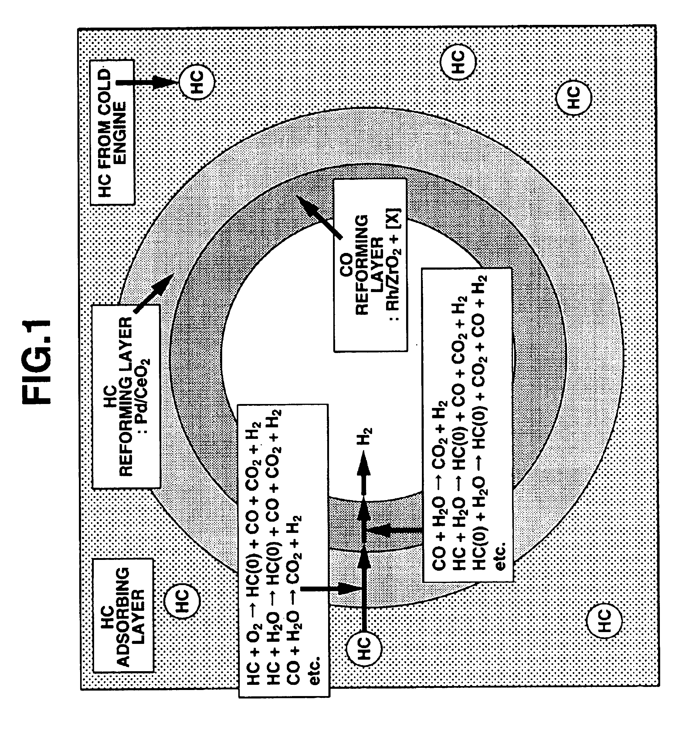
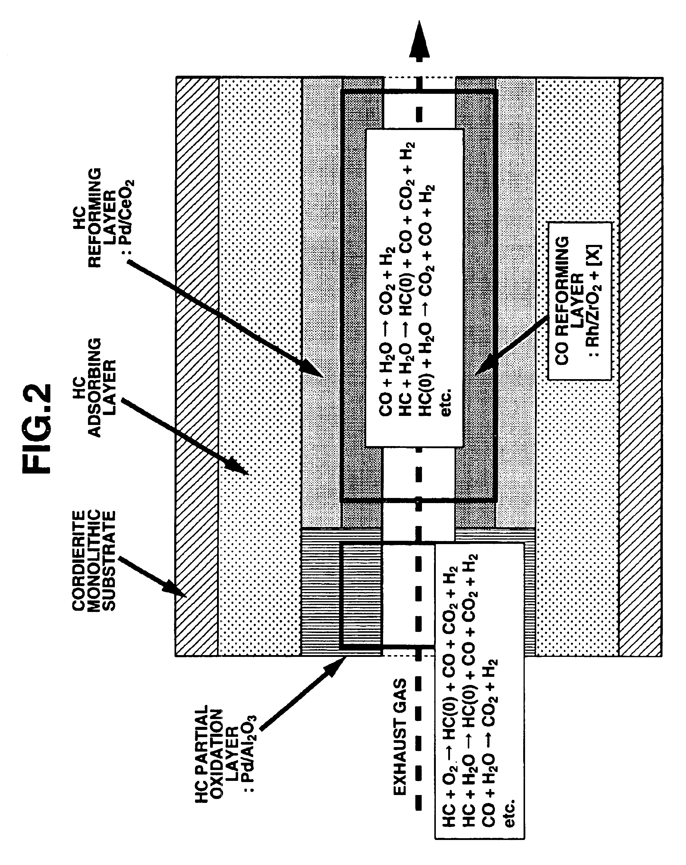
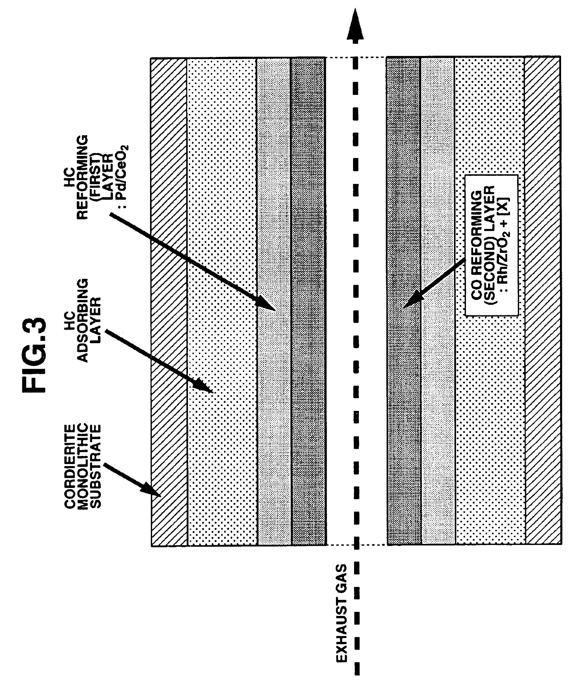
An exhaust gas purifying catalyst for purifying exhaust gas discharged from an automotive internal combustion engine. The exhaust gas purifying catalyst comprises a monolithic substrate. A HC adsorbing layer for adsorbing hydrocarbons (HC) is formed on the monolithic substrate. The HC absorbing layer contains zeolite. A catalytic layer for producing hydrogen (H2) and reducing NOx is formed on the HC adsorbing layer. The catalytic layer functions to produce hydrogen (H2) from at least one of hydrocarbons and carbon monoxide (CO) and to reduce nitrogen oxides (NOx) with the produced hydrogen and at least one of hydrocarbons and carbon monoxide in exhaust gas.

Description

FIELD OF THE INVENTION[0001]This invention relates to improvements in an exhaust gas purifying catalyst, and more particularly to improvements in an exhaust gas purifying catalyst for effectively reducing nitrogen oxides in an oxygen-excessive exhaust gas.BACKGROUND TECHNIQUE[0002]Hitherto catalysts for simultaneously oxidizing carbon monoxide (CO) and hydrocarbons (HC) and reducing nitrogen oxides (NOx) have been extensively used as exhaust gas purifying catalysts installed to internal combustion engines of automotive vehicles and the like. A typical example of these catalysts is disclosed in Japanese Patent Publication No. 58-20307, in which an alumina coat layer is formed on a refractory substrate and contains noble metals such as Pd, Pt and / or Rh and additionally contains, as assistant catalyst, oxides of rare earth metal such as Ce and / or La and / or of base metal such as Ni, if necessary.[0003]However, such a catalyst is largely affected by an exhaust gas temperature and a set a...

Claims


Application Information

Patent Timeline
IPC IPC(8): B01J23/63B01D53/94B01J23/54B01J37/00B01J37/02B01J21/06B01J21/00B01J23/46F01N3/08B01D53/34B01D53/81B01J29/08B01J29/40B01J29/70B01J29/74B01J29/80B01J37/025F01N3/10F01N3/24F01N3/28
CPCB01D53/9418B01D53/9495B01J23/63B01J37/0244B01J37/0246B01D53/945Y02T10/24B01D2251/204B01D2251/208B01D2255/9022B01D2255/912B01J21/066B01J23/464B01J29/084B01J29/40B01J29/7007B01J29/7415B01J29/80B01J37/0248Y02T10/22Y02T10/12B01D53/94
Inventor YAMAMOTO, SHINJI
Owner NISSAN MOTOR CO LTD
Learn More