

Interferometry system having a dynamic beam steering assembly for measuring angle and distance
a technology of dynamic beam steering and interferometer, which is applied in the field of interferometers to achieve the effects of reducing the bandwidth of electronics, reducing the likelihood of depolarization, and minimizing transverse displacemen
- Summary
- Abstract
- Description
- Claims
- Application Information
AI Technical Summary
Benefits of technology
Problems solved by technology
Method used
Image

Examples
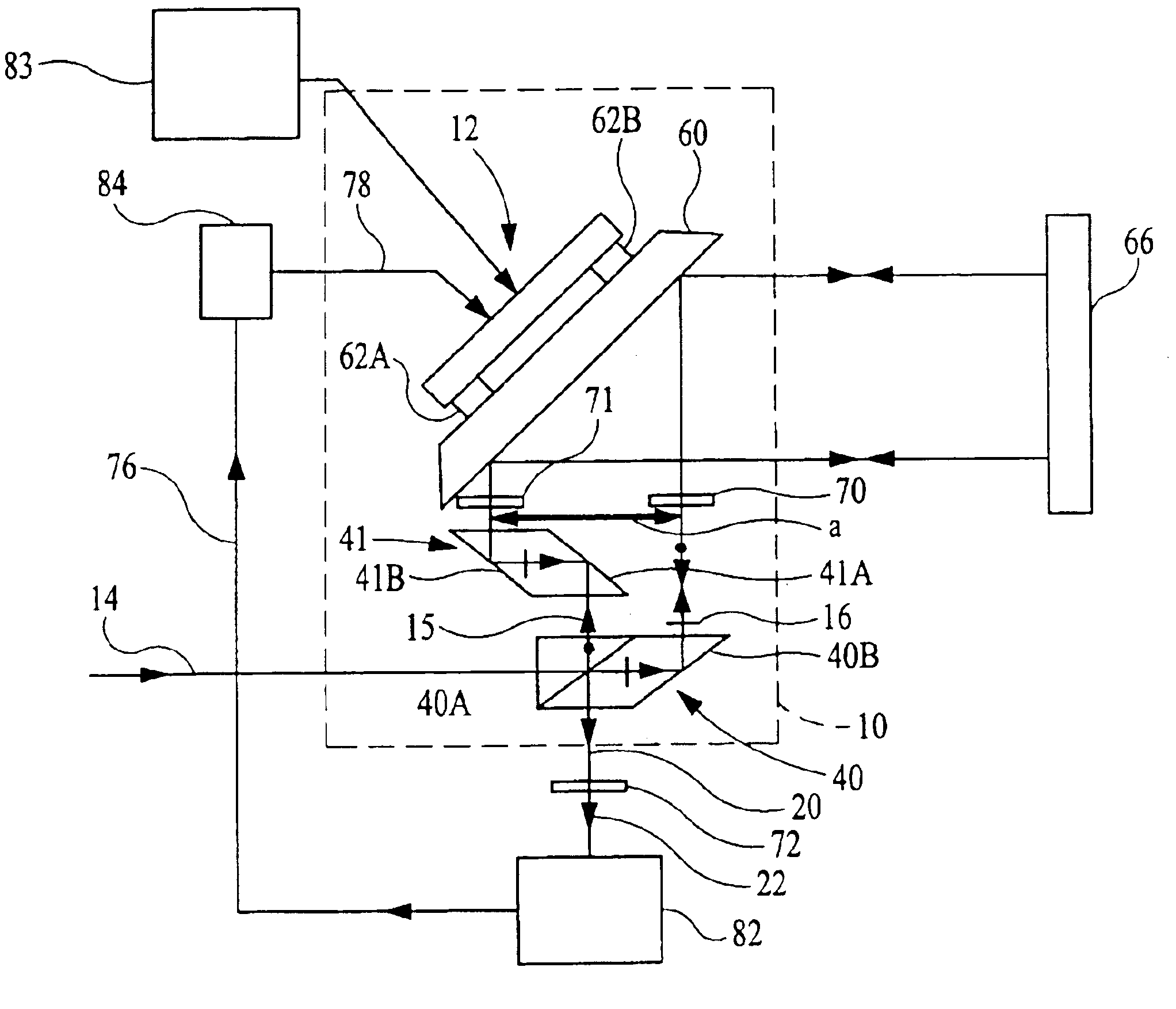
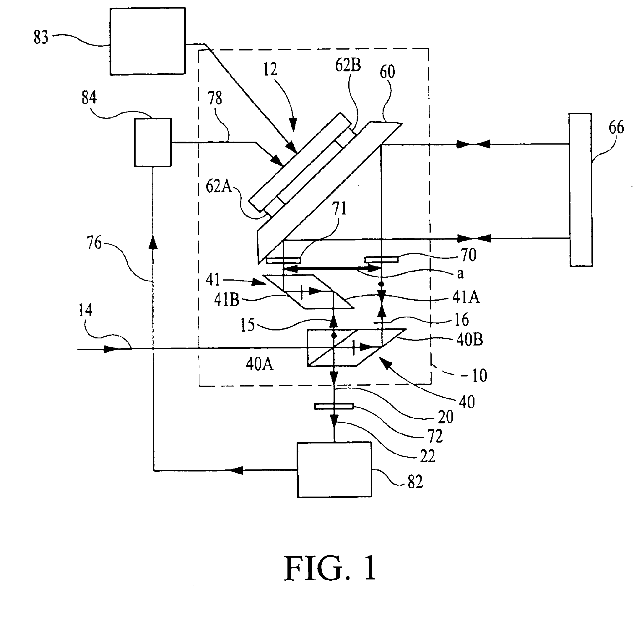
first embodiment
where i is an index denoting reference to a particular embodiment, and where Λi comprises the nonlinear errors including in particular cyclic error terms and phase offset ζi comprises all contributions to phase αi that are not related or associated with the optical path of the measurement and reference paths and not related to the nonlinear errors. Phase offset ζ1 is generally considered a constant in the invention and is measured and / or monitored as required by an end use application using known techniques.
[0081]Phase φ1 is given by the formula
φ1=k[∫Mnds−∫Rnds] (6)
where the integrals are line integrals with respect to the infinitesimal optical path length nds along the measurement and reference paths indicated by M and R, respectively, and n is the refractive index of the infinitesimal physical path length ds at the wavelength λ of input beam 14. Phase φ1 is also related to the deviation from normal incidence δθ1 of the reference and measurement beams on stage mirror 66 in the pl...
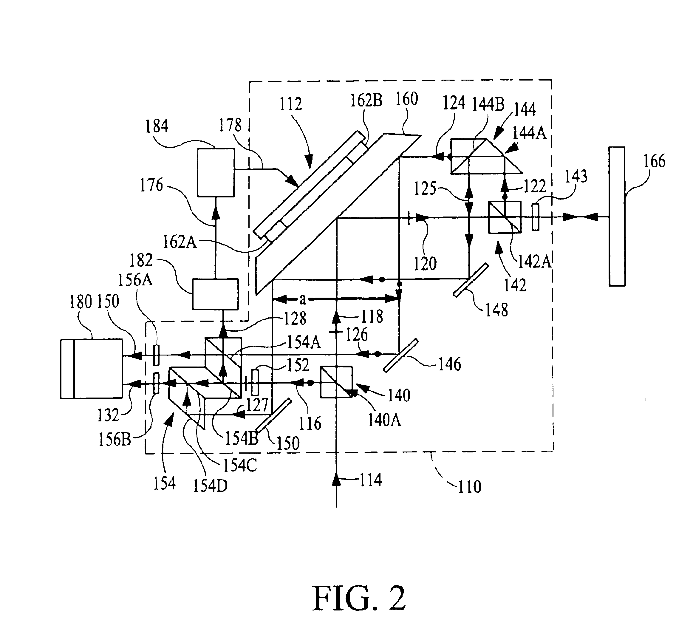
second embodiment
[0089]Gas in a reference path and / or measurement path can introduce an error in the angular orientation of measurement object mirror 66 inferred from the angular orientation of beam-steering mirror 60 due to the effects of density gradients in the gas. Density gradients in the gas alter the directions of propagation of reference and / or measurement beams propagating through the gas. For further description of the error in angular orientation, see the description of corresponding effects of gas given for the present invention.
[0090]A variant of the first embodiment is described in which an angular displacement of an object in two orthogonal planes is measured and monitored. The variant of the first embodiment comprises the same input beam 14 and interferometer system 10 plus an additional set of optical elements, detector and signal processor system, and beam-steering assembly transducers. The additional set of optical elements comprise elements the same as elements 40, 41, 70, and 71...
fourth embodiment
[0141]The description first output beam 438, detector 476, and signal 444 is the same as corresponding portions of the description given of beam 338, detector 376, and signal 344 of the Alternatively, detector 476 may comprise angular displacement interferometer(s) to measure changes in directions of propagation of the reference and / or measurement beam components of first output beam 438. Each of the angular displacement interferometers is based on one of the angular displacement interferometers subsequently described herein.
[0142]Interferometer system 400 and stage mirror 462 introduce a phase shift φ6 between the measurement and reference beam components of the second output beam 440 and mixed output beam 442. A detector 480 measures the intensity of mixed output beam 442, e.g., preferably by photoelectric detection, to produce electrical interference signal or electrical heterodyne signal s6. Heterodyne signal s6 is transmitted to electronic processor and computer 482 in either ...
PUM
 Abstract
Description
Claims
Application Information