Solid-state laser oscillator with gain media in active mirror configuration

a laser oscillator and gain media technology, applied in laser cooling arrangements, laser details, optical resonator shape and construction, etc., can solve the problems of reducing the beam quality, reducing the design flexibility of the beam, so as to improve the design flexibility, and improve the effect of transverse mode control

Inactive Publication Date: 2005-05-03
THE BOEING CO
View PDF30 Cites 26 Cited by
  • Summary
  • Abstract
  • Description
  • Claims
  • Application Information

AI Technical Summary

Benefits of technology

[0037]A first preferred embodiment of the present invention comprises a SSL with an array of AMA modules placed in a linear unstable resonator that provides a large fundamental mode size, excellent transverse mode control, and collimated output beam. A second preferred embodiment of the present invention comprises a SSL with an array of AMA modules placed in a ring unstable resonator that provides much increased design flexibility and an increased number of design possibilities, longer collimated beam regions, and which avoids spatial hole burning. A third prefer

Problems solved by technology

Thermomechanical effects present a major challenge to developing a solid-state laser (SSL) for generation of high-average power (HAP) with near diffraction-limited beam quality (BQ).
In particular, distortions to optical phase fronts caused by transverse temperature gradients within a SSL gain medium degrade beam quality (BQ) and render the output beam useless for many important applications.
Using such a stable resonator is entirely inappropriate for use with a large aperture AMA gain medium.
One challenge associated with lasers employing a gain medium with a large optical aperture is designing a resonator supporting a low order (preferably TEMoo) mode(s) that can efficiently fill the entire aperture.
Forty years of laser development has shown that obtaining high-average power output with good BQ from a solid-state laser with conventional stable resonators poses almost insurmountable problems.
Stable resonators with long cavity

Method used


Image

  • Solid-state laser oscillator with gain media in active mirror configuration
  • Solid-state laser oscillator with gain media in active mirror configuration
  • Solid-state laser oscillator with gain media in active mirror configuration

Examples


first embodiment

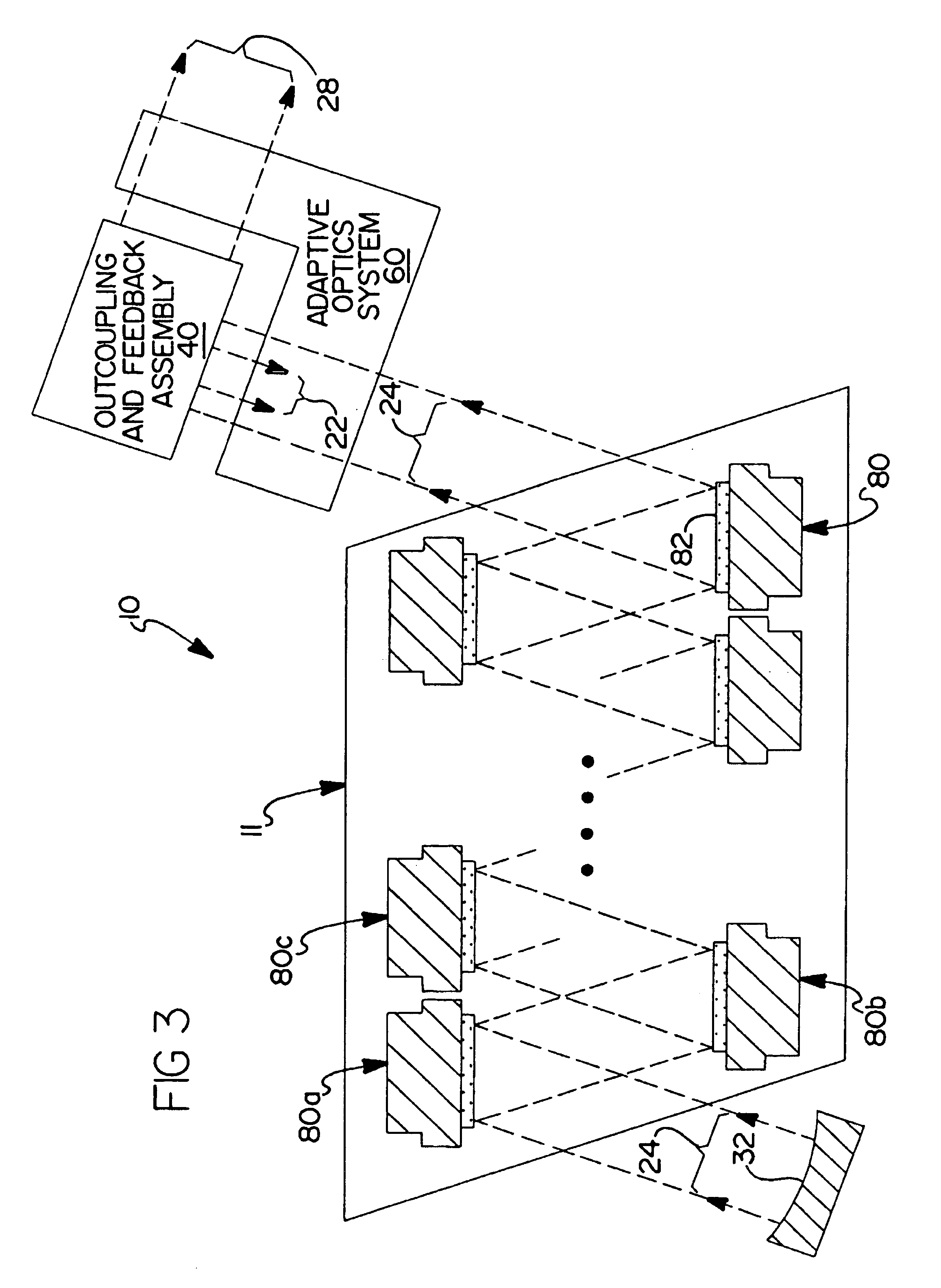
[0079]Referring now to FIG. 7, there is shown a solid-state laser oscillator 100 in accordance with a second alternative preferred embodiment of the present invention. The SSL oscillator 100 comprises a laser gain assembly 111 placed in a ring unstable resonator formed by mirrors 134,135, 136, 138, and outcoupling / feedback assembly 140. The laser gain assembly 111 is generally the same as that used with the present invention shown in FIG. 3.

[0080]A portion of the collimated laser beam 24 propagating from laser gain assembly 111 and entering the outcoupling and feedback assembly 140 is coupled out of the oscillator 100 forming an outcoupled laser beam 28. A portion of the laser beam 28 not coupled out of the oscillator 100 forms a feedback beam 22, which is directed by successive reflections from mirrors 136, 134, 135, and 138 back into the laser gain assembly 111. Mirrors 136 and 138 are preferably flat. Mirrors 134 and 135 are convex and concave, respectively. Their curvatures are ...

second embodiment

[0085]A variation of the present invention may use an alternate configuration of the beam expansion telescope. FIG. 9 shows a telescope beam expansion telescope 130a formed by mirrors 134a and 135a, both having concave surfaces. Mirrors 134a and 135a are suitable for receiving the collimated feedback beam 22 and expanding it into the collimated beam 24 with transverse dimensions suitable to fill the optical aperture in AMA modules 80 of the laser gain assembly 111. A ring unstable resonator employing this type of beam expander is usually referred to as a “negative branch.” One advantage of this configuration is that a filtering aperture 139 may be placed at the laser beam focus between mirrors 134a and 135b for the purpose of removing undesirable higher order TEM. Such an aperture may also be beneficial for suppressing an optical wave traveling around the ring resonator in the reverse (i.e., clockwise) direction. Other advantages include using mirrors having a shorter radius of curv...

fifth embodiment

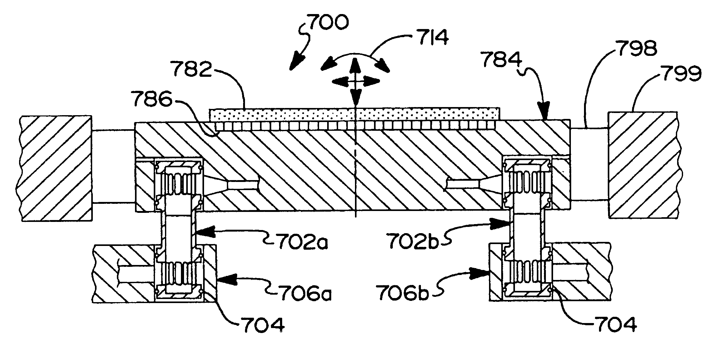
[0092]End sections 502a and 502b may have apertures as may be required, for example, to allow passage of a laser beam, electrical wiring and coolant connections. Aperture 509 in end section 502b is an example of such an aperture for the passage of a laser beam. When practiced with the present invention, central opening 508 may be used to allow passage of a laser beam (for example, between mirrors 134 and 136, and 135 and 138a), and / or electrical wiring and coolant connections.

[0093]FIG. 14 shows an optical bench 600 of alternate construction. Optical bench 600 comprises two annular end sections 602a and 602b similar to end sections 502a and 502b used with the optical bench 500 placed on a common axis of symmetry 604 and held in position by a plurality of struts 605. Struts 605 are anchored to the end sections 602a and 602b via joints 603. Preferably, end sections 602a and 602b are made of aluminum honeycomb or another suitably strong and lightweight material. Struts 605 are preferab...


PUM


Abstract

An apparatus and method for achieving a near diffraction-limited, high-average power output from a solid-state laser oscillator are provided. The solid-state laser uses multiple disk-shaped laser gain media having a large optical aperture placed in an unstable resonator. The laser gain media is provided with optical coatings for operation in the active mirror configuration and is attached to a rigid, cooled substrate, which allows it to maintain a prescribed shape even when experiencing significant thermal load. The resonator is configured so as to preferentially support low order optical modes with transverse dimensions sufficiently large to efficiently fill the gain media apertures. Resonator configurations capable of producing standing wave or traveling wave optical fields are disclosed. The resonator may include means for intracavity correction of an optical phase front by adaptive optics. Also disclosed is an arrangement of resonator gain elements in axisymmetric arrays suitable for integration into a compact and lightweight laser system.

Description

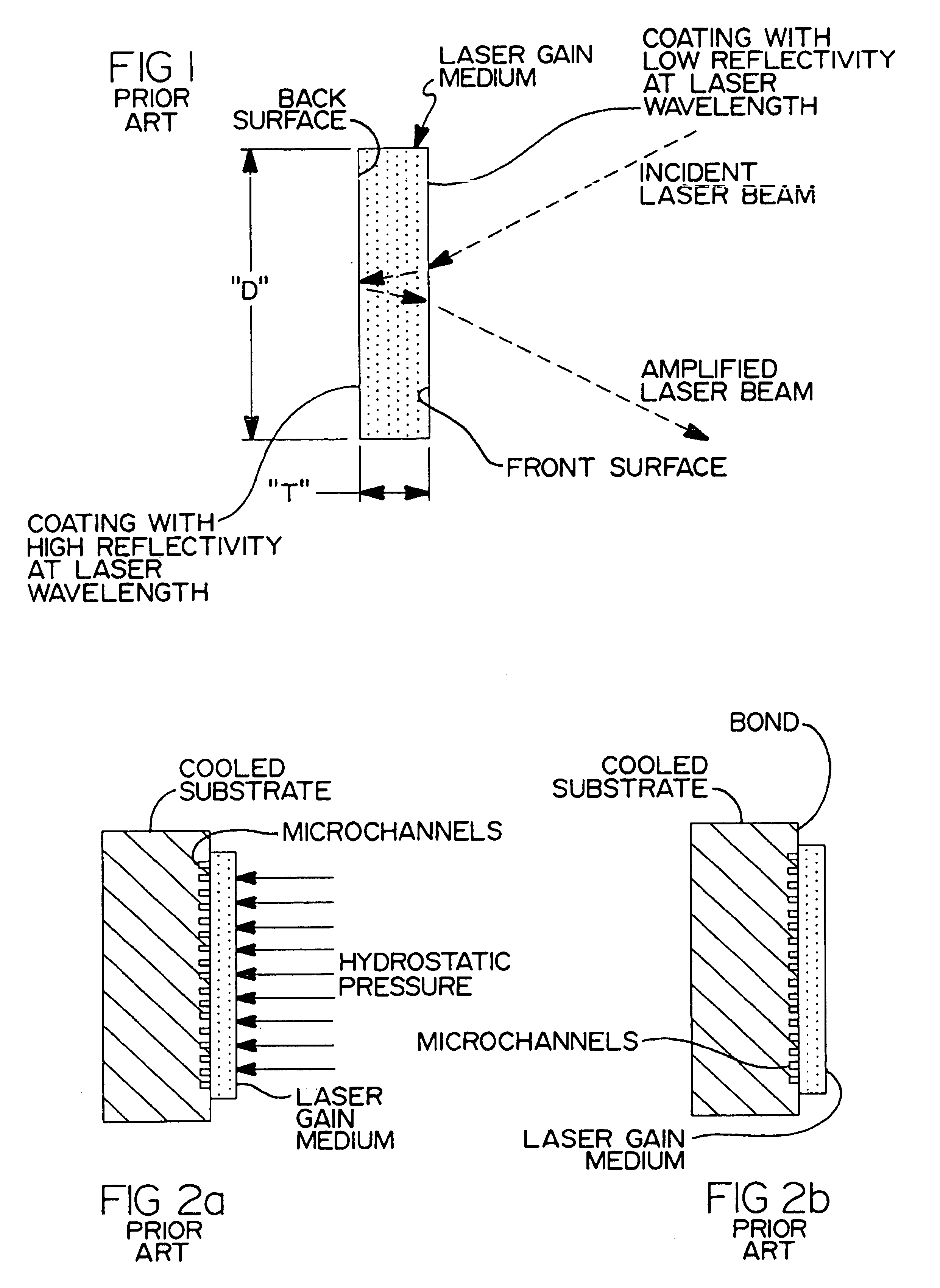
CROSS REFERENCE TO RELATED APPLICATIONS[0001]This application is a divisional of U.S. Ser. No. 09 / 861,363; filed May 18, 2001 now U.S. Pat. No. 6,603,793, presently allowed.BACKGROUND OF THE INVENTION[0002]Thermomechanical effects present a major challenge to developing a solid-state laser (SSL) for generation of high-average power (HAP) with near diffraction-limited beam quality (BQ). In particular, distortions to optical phase fronts caused by transverse temperature gradients within a SSL gain medium degrade beam quality (BQ) and render the output beam useless for many important applications. A class of SSL known as “active mirror amplifier” (AMA) has shown effective reduction of transverse temperature gradients and demonstrated generation of laser output with very good BQ. A general configuration of a laser gain medium in an active mirror (amplifier) configuration is disclosed in the prior art illustration of FIG. 1.[0003]The AMA was first disclosed by Almasi et al. in U.S. Pat. ...

Claims


Application Information

Patent Timeline
IPC IPC(8): H01S3/06H01S3/08H01S3/081
CPCH01S3/042H01S3/0604H01S3/025H01S3/0615H01S3/105H01S3/08059H01S3/0813H01S3/0818H01S3/083H01S3/07
Inventor VETROVEC, JAN
Owner THE BOEING CO
Why Eureka
Try Eureka