Brush DC motors and AC commutator motor structures with concentrated windings

a commutator motor and brush technology, applied in the direction of dynamo-electric machines, rotary current collectors, electrical apparatus, etc., can solve the problems of unintended heating of coils and brushes, poor commutation, unfavorable commutation, etc., to reduce the inductance value of each simple coil, reduce the number of turns, and improve the effect of current commutation

Inactive Publication Date: 2005-05-10
QUEBEC METAL POWDERS
View PDF27 Cites 27 Cited by
  • Summary
  • Abstract
  • Description
  • Claims
  • Application Information

AI Technical Summary

Benefits of technology

[0010]This invention is an armature winding of a DC or AC commutator motor, which eliminates the problem of the interlocking of the coils and the problem of circulating currents. All the path voltages are perfectly balanced and the current commutation is improved when compared to the classical structures.
[0011]In this invention, the number of commutator segments is higher than the number of rotor teeth, and a plurality of simple coils are wound around the same tooth. The leads of each coil are connected to different segments of the commutator. Use of the present invention reduces the number of turns per coil for a same value of the DC voltage supply and a same speed range of the motor. The parallel paths of the armature winding can be perfectly balanced. An equal current distribution through the parallel circuits of the armature is maintained and there is no circulation current between these parallel circuits. The inductance value of each simple coil is reduced and consequently the commutation problems are minimized when compared to the case of a concentrated winding with only one coil wound around each tooth. The copper volume of the end-windings, the Joule losses and the axial length of the motor armature are lower than in the case of a lap or a wave winding with interlocking coils. It is also possible to arrange connections of the leads of each coil to the commutator segments to obtain balanced emf in the different coil paths between brushes. These structures can be used efficiently for motors over a wide range of power, and their cost of realization is lower than the cost of classical structures.
[0012]In accordance to this invention, two kinds of structures are presented: structures with a regular distribution of rotor teeth with identical dimensions, and structures with a regular distribution of rotor teeth with different dimensions. Both structures are efficient in terms of performance and cost of realization. The values of the winding coefficients of these structures (i.e. the ratio between the fundamental component of magnetic flux embraced by the winding and the total magnetic flux per pole) are high.
[0013]The performance of the structures proposed in accordance with the present invention is similar to the performance of the classical structures in terms of current commutation. But the performance of the structures proposed in accordance with the present invention in terms of torque to winding volume ratio is higher than the performance of the classical structures. With the proposed structures, the volume of copper is reduced, the Joules losses (copper losses) and the weight are minimized. The total axial length of the motor is reduced. The efficiency is improved and is higher than in the case of classical structures. The structures of the winding and the magnetic circuit, which are proposed in accordance with the present invention, are also easier to realize. The total cost of the motor is then minimized.

Problems solved by technology

The most significant problem with using a lap winding is that the voltages induced in the different parallel paths are unequal.
Because of the imbalance in induced voltages, circulating currents appear in the windings and through the brushes.
These circulating currents cause unnecessary heating of the coils and brushes and tend to produce poor commutation.
In a wave winding, the problem of the circulating currents due to the unbalanced voltages of the parallel paths is minimized but it is also impossible to get perfectly balanced voltages.
However, the concentrated winding technique is too often associated and restricted to windings with a short pitch, i.e. windings with lower performances than the performances of the classical winding structures.
The main drawbacks of this motor structure are its low performance in terms of torque to weight ratio, torque ripple, and poor commutation performance if the power is increased.
With this structure, the induced voltages in the coil paths between brushes are not always balanced.
This unbalanced condition of operation produce supplementary losses, torque ripples, mechanical vibrations and commutation problems.

Method used


Image

  • Brush DC motors and AC commutator motor structures with concentrated windings
  • Brush DC motors and AC commutator motor structures with concentrated windings
  • Brush DC motors and AC commutator motor structures with concentrated windings

Examples


Embodiment Construction

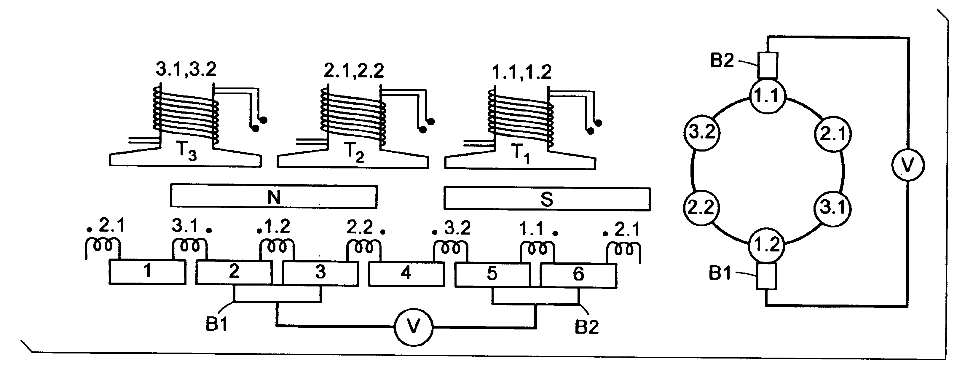
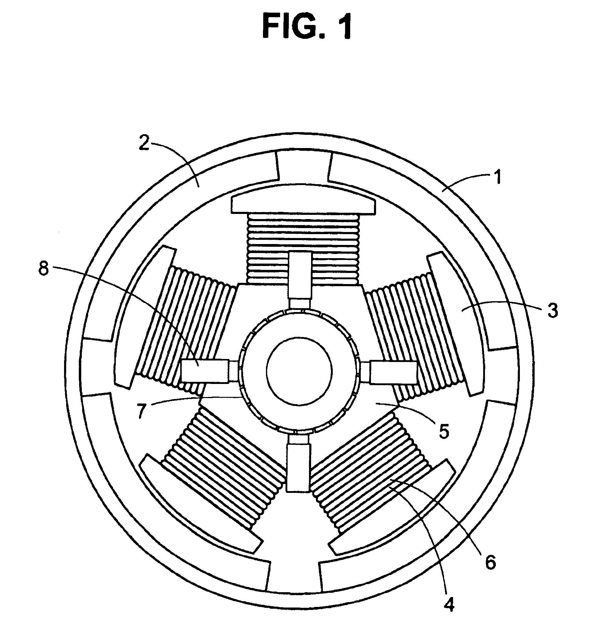
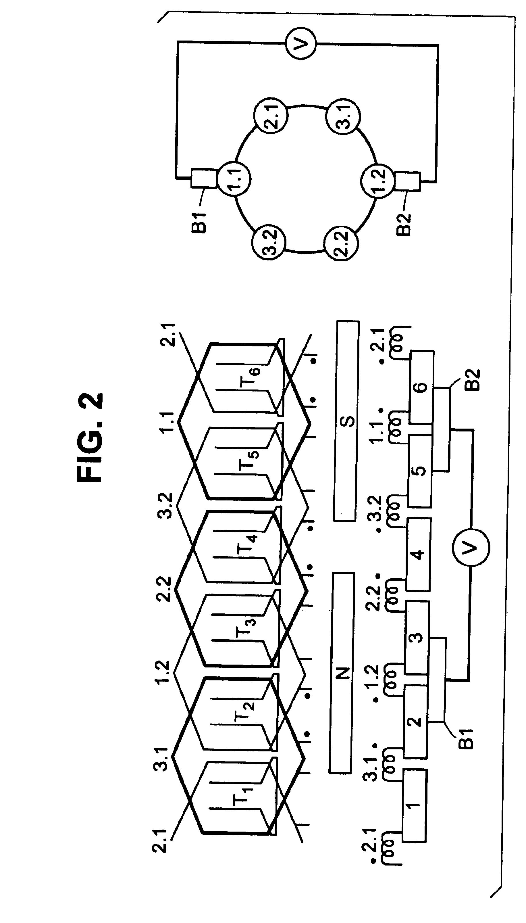
[0038]In one embodiment of the present invention, the rotor has a regular distribution of rotor teeth with identical dimensions, and there are 2P poles, magnetized alternatively North and South in the stator. These poles can be constructed with segments of permanent magnet mounted on the surface of a core made of soft magnetic material or with coils wound around teeth made of soft magnetic material and fed by a DC or AC current. The rotor core has S slots. The simple coils of the rotor are wound around S teeth or in some case around S / 2 teeth only. There are z segments on the commutator which are connected to the terminals of the coils. 2B brushes are sliding on the commutator surface when the rotor is rotating. The characteristics of these machines respect the following conditions:

[0039]

P is an integer and0 S = 2P + AA is an integer equal to −1 or 1 or 2 or S > 2Z = k*LCM(S,2P) ± nk is an integer greater than 0LCM is the Least Common Multiple of S and 2Pn is equal to 0 or kB = P or...


PUM

PropertyMeasurementUnit
torque-weight ratioaaaaaaaaaa
soft magneticaaaaaaaaaa
axial lengthaaaaaaaaaa

Abstract

Structures of direct current motors or ac commutator (Universal) motors which use a concentrated winding on the rotor with coils wound around the teeth. The number of commutator segments is higher than the number of rotor teeth. Several coils are wound around the same tooth. The terminals of the coils are connected to different segments of the commutator. The parallel paths of the armature winding are perfectly balanced. An equal current distribution through the parallel circuits of the armature is maintained and there is no circulation current between these parallel circuits. The problems related to commutation are reduced because the value of the coil inductances is low. The copper volume of the end-windings, the Joule losses and the axial length of the motor armature are lower than a lap or a wave winding with interlocked coils. Two kinds of structures with a concentrated winding are presented: some with rotor teeth with identical dimensions and some with rotor teeth with different dimensions.

Description

BACKGROUND OF THE INVENTION[0001]This invention relates to direct current motors or AC commutator (Universal) motors. More particularly, this invention relates to such motors which use a concentrated winding on the rotor with coils wound around the teeth.[0002]In conventional DC motors or AC commutator (Universal) motors, there are three types of rotor armature windings: lap windings, wave windings and frog-legs windings. These windings are made with simple coil elements which are always interlocked. With an interlocked winding, the ratio between the axial length of the end-windings and the axial length of the armature magnetic circuit is relatively high as it is described by Klein U.S. Pat. No. 4,329,610, Ban et al. U.S. Pat. No. 4,197,475 and Ikeda U.S. Pat. No. 4,437,028.[0003]All these windings differ primarily by the method which is used to connect the terminals of the simple coils to the commutator. A lap winding is also known as a multiple winding and for this kind of winding...

Claims


Application Information

Patent Timeline
Patent Type & Authority Patents(United States)
IPC IPC(8): H02K23/26H02K23/30
CPCH02K23/30Y10T29/49012H02K21/16H02K1/146H02K3/18H02K3/28
Inventor CROS, JEROMEVIAROUGE, PHILIPPE
Owner QUEBEC METAL POWDERS
Why Eureka
Try Eureka