
Optical switch systems using waveguide grating-based wavelength selective switch modules

Inactive Publication Date: 2005-05-10
INTEGRATED OPTICS COMM
View PDF40 Cites 9 Cited by
  • Summary
  • Abstract
  • Description
  • Claims
  • Application Information

AI Technical Summary

Benefits of technology

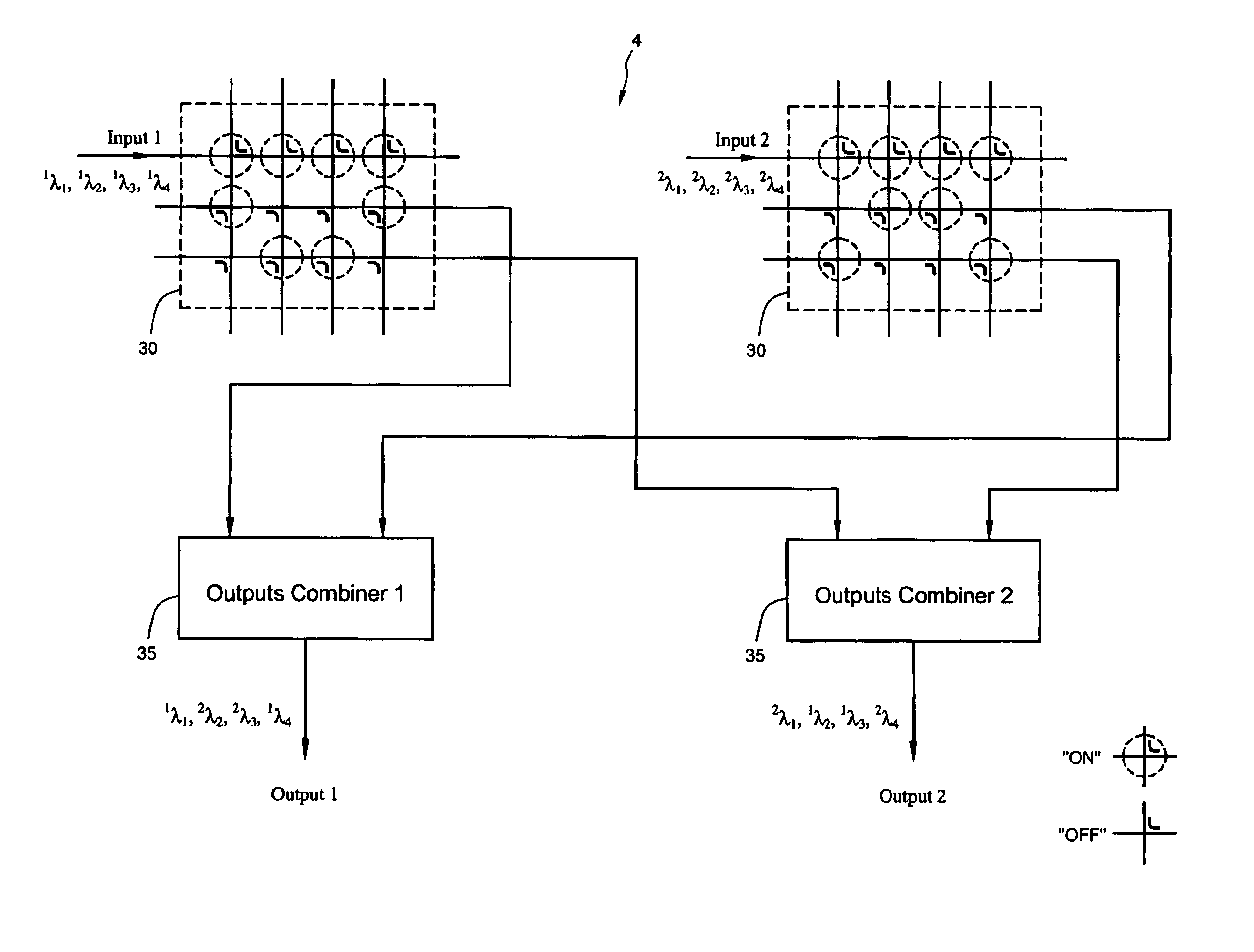
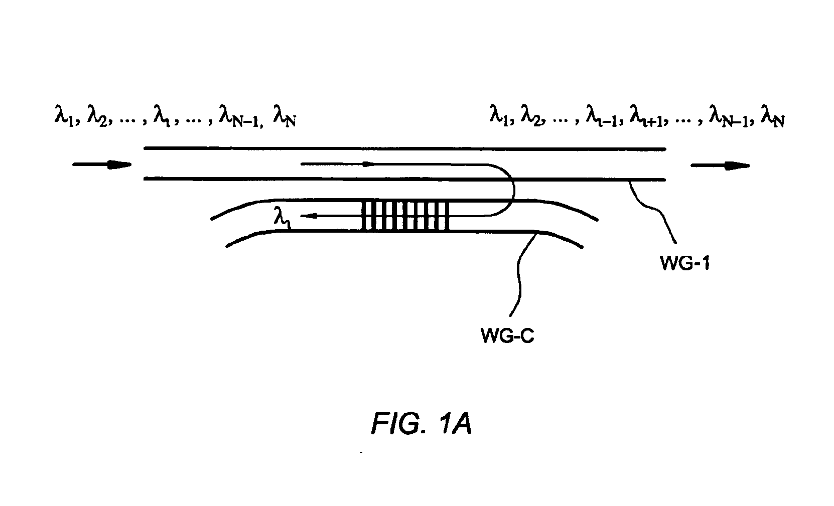
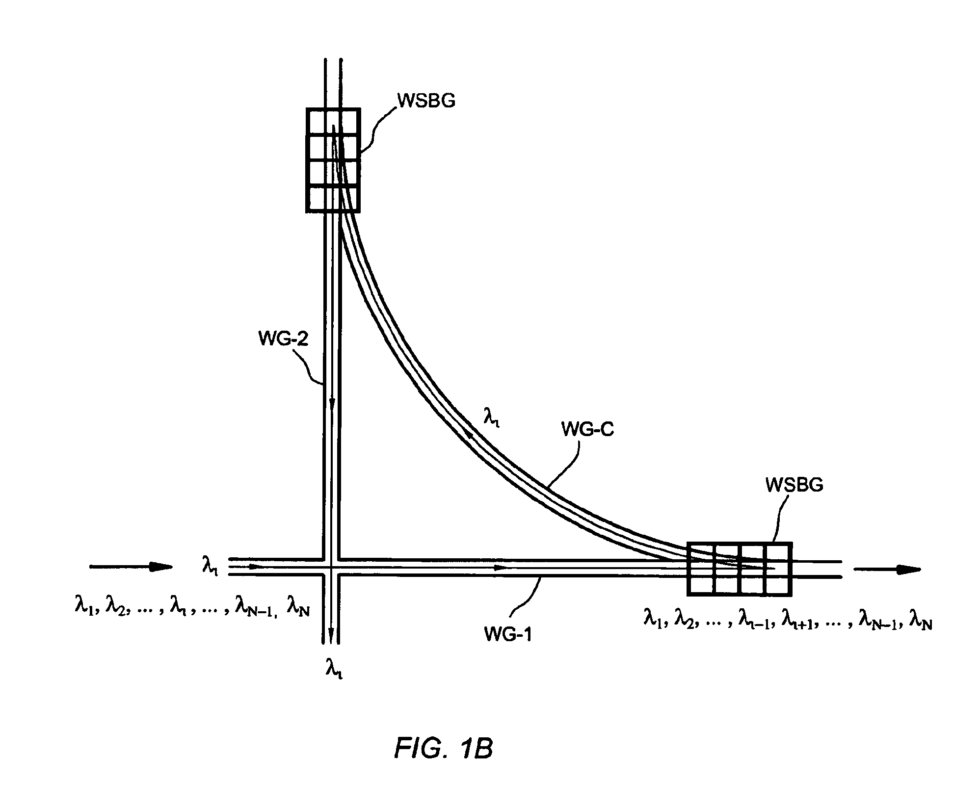
[0015]The present invention discloses methods and apparatus for constructing optical switch systems. These methods and apparatus greatly simplify the structure of large-scale optical switches, compared with known approaches. The methods and apparatus also provide advantages of configuration flexibility, modular construction, constant signal loss, and minimal required numbers of switch units. The optical switch systems are built upon the optical switch modules—another embodiment of this invention. The switch systems comprise M×N switch modules and the switch module in turn comprises a two-dimensional waveguide array and a number of waveguide grating-based wavelength selective switches.
[0016]The optical switch module is very flexible in its applications. It can be used as a matrix switch, a de-multiplexer, or a re-multiplexer. With the capability of wavelength-selective routing provided by the switch modules, the optical switch systems disclosed in this invention requires a relatively small amount of switch units to extend into a very-large-scale switch system. The optical switch systems also eliminate unbalanced power loss, simplify the fabrication and packaging processes, reduce the insertion loss and power consumption, and further improve overall reliability. In accordance with the invention, the switch system constructed by the method disclosed performs the de-multiplexing and re-multiplexing functions inherently. Therefore, in one embodiment, no external de-multiplexers and complicated re-multiplexers are needed to form an optical switching functional block. The size and cost of the optical switches are significantly reduced.

Problems solved by technology

Current optical switching and signal transmission systems are limited to optical switching of an entire spectrum without wavelength differentiation or selection.
This requirement leads to more complicated system configurations, higher manufacture and maintenance costs, and lower system reliability.
For this reason, even though optical switches are advantageous because the optical signals are switched entirely in the optical domain without converting them into the electrical domain, the cost and size of such optical switches can be prohibitive for many applications.
However, with current technical limitations, an all fiber network implemented with optical switches are still quite expensive.
However, in these switches, light travels through free space, which causes unbalanced power loss.
Further, in order to steer each mirror, multiple electrodes need to be connected to each mirror, which increases manufacturing complexity, particularly for large-scale mechanical-type MEMS-based switches.
Finally, alignment and packaging are problematical for large-scale switches.
However, these types of switches have not been proven to be completely reliable.
Further, these switches often result in insertion loss for large-scale switches.
A common drawback of both of these two types of MEMS-based switches is the requirement to work with external de-multiplexing and re-multiplexing systems in order to function properly in an optical networking system.
The requirements of implementing de-multiplexing and re-multiplexing functions add tremendous complexities to the system configuration and significantly increase the cost of manufacture, system installation, and maintenance of the optical network systems.
Another drawback of both of these two types of MEMS-based switches is that these prior art switching systems are not wavelength selective switches.
In other words, the switching systems cannot selectively switch a particular wavelength from an input waveguide to a desired output waveguide.
Current optical switch systems have serious drawbacks and practical limitations.
Drawbacks of this type of switch system include: (1) a large number of couplers are required to scale up the matrix and (2) the insertion loss of signals at various input ports varies greatly.

Method used


Image

  • Optical switch systems using waveguide grating-based wavelength selective switch modules
  • Optical switch systems using waveguide grating-based wavelength selective switch modules
  • Optical switch systems using waveguide grating-based wavelength selective switch modules

Examples


Embodiment Construction

[0023]In the following description, numerous specific details are provided, such as the identification of various system components, to provide a thorough understanding of embodiments of the invention. One skilled in the art will recognize, however, that the invention can be practiced without one or more of the specific details, or with other methods, components, materials, etc. In still other instances, well-known structures, materials, or operations are not shown or described in detail to avoid obscuring aspects of various embodiments of the invention.

[0024]Reference throughout this specification to “one embodiment” or “an embodiment” means that a particular feature, structure, or characteristic described in connection with the embodiment is included in at least one embodiment of the present invention. Thus, the appearance of the phrases “in one embodiment” or “in an embodiment” in various places throughout this specification are not necessarily all referring to the same embodimen...


PUM

PropertyMeasurementUnit
Flexibilityaaaaaaaaaa
Selectivityaaaaaaaaaa

Abstract

The present invention discloses methods and apparatus for constructing optical switch systems, in which any input optical signals can be routed to any output ports. The methods and apparatus provide advantages of configuration flexibility, modular construction, constant signal loss, and minimal numbers of switch units required. The switch systems comprise M×N switch modules. The switch module in turn comprises a two-dimensional waveguide array and a number of waveguide grating-based wavelength selective switches. With the capability of wavelength-selective routing provided by the switch modules, the optical switch systems requires a relatively small amount of switch units to extend into a very-large-scale switch system.

Description

CROSS-REFERENCE TO RELATED APPLICATION[0001]Priority is hereby claimed under 35 U.S.C. § 120 to U.S. Provisional Patent Application Ser. No. 60 / 348,927 filed Oct. 22, 2001, U.S. Provisional Patent Application Ser. No. 60 / 346,066 filed Jan. 3, 2002, U.S. Provisional Patent Application No. 60 / 346,567 filed Jan. 8, 2002, U.S. Provisional Patent Application Ser. No. 60 / 373,803 filed Apr. 19, 2002, U.S. patent application Ser. No. 10 / 104,273 filed Mar. 22, 2002, U.S. patent application Ser. No. 10 / 177,632 filed Jun. 19, 2002, U.S. patent application Ser. No. 10 / 188,955, filed Jul. 3, 2002, U.S. patent application Ser. No. 10 / 190,018, filed Jul. 5, 2002, and U.S. patent application Ser. No. 10 / 202,054, filed Jul. 23, 2002, each of which is hereby incorporated by reference in its entirety.BACKGROUND OF THE INVENTION[0002]1. Field of the Invention[0003]This invention relates generally to optical switching systems, and more particularly, to a method and apparatus for routing input signals in...

Claims


Application Information

Patent Timeline
IPC IPC(8): A61K31/63A61K31/40A61K31/44C07C311/00C07C311/39C07C311/49C07D209/14C07D209/00G02B6/124G02B6/28G02B6/12G02B6/125G02B6/35G02B6/34H04Q11/00
CPCA61K31/40A61K31/63C07C311/39C07C311/49C07D209/14G02B6/12004G02B6/12007G02B6/124G02B6/125G02B6/2821G02B6/29319G02B6/29334G02B6/3546G02B6/4215H04Q11/0005A61K31/44H04Q2011/0058G02B6/2852G02B6/35G02B6/3508G02B6/357G02B6/3596G02B2006/12107G02B2006/12145H04Q2011/0016H04Q2011/0024H04Q2011/0032
Inventor ZHANG, JIANJUNLING, PEICHINGCHEN, JINLIANGXU, MING
Owner INTEGRATED OPTICS COMM
Learn More