High performance muffler

a high-performance, muffler technology, applied in the field of mufflers, can solve the problems of exhaust noise, rare use of absorption materials, and low sound attenuation, and achieve excellent sound attenuation and reduce backpressure

Inactive Publication Date: 2005-05-17
AGENCY FOR SCI TECH & RES
View PDF28 Cites 15 Cited by
  • Summary
  • Abstract
  • Description
  • Claims
  • Application Information

AI Technical Summary

Benefits of technology

[0006]A muffler for use in attenuating a sound induced by or associated with a gas produced by a machine includes an elongated body having a first axis along its length and including a first partition for defining an inlet chamber. The body has an inlet opening on a side of the body and an outlet opening at one end of the body. An inlet pipe connects to the side of the body at the inlet opening and delivers the gas into the inlet chamber. The side inlet pipe is oriented at an angle to the first axis greater than zero degrees. In a preferred example embodiment, the inlet pipe is connected to the inlet opening at an angle substantially greater than zero degrees, such as 90 degrees. An outlet pipe connected to the outlet opening discharges muffled gas from the body. In a preferred example embodiment, the one end of the inlet pipe is flared. The side inlet pipe as well as its flared end permit attenuation of the gas sound by the muffler without increasing back pressure associated with that sound attenuation in a direction opposite to that of the gas flowing in the inlet pipe.
[0010]In a specific implementation, a high performance reactive exhaust muffler for an internal combustion engine has a high acoustic performance-to-weight ratio and maintains a low backpressure to the engine. The muffler includes a muffler body generally cylindrical in shape. A side inlet pipe is flared at its interface with the muffler body and is preferably perpendicular to a longitudinal axis of the muffler body. The exhaust gas flows through the flared inlet opening into an inlet chamber where it experiences a first expansion. This side inlet pipe design gives a much larger expansion ratio compared to conventional end-in inlet pipe designs, and therefore, has better sound attenuation performance.
[0013]The muffler design is based on knowledge gained through studies and numerical simulations of duct acoustics and flow dynamics. The muffler achieves excellent levels of sound attenuation while appreciably reducing backpressure at least relative to conventional mufflers. The muffler may also be retrofitted to the exhaust system of existing motorized vehicles, e.g., trucks, automobiles, vans, and in general all kinds of motorized vehicles. Indeed, the muffler finds advantageous application to any muffler system including, for example, the internal combustion engines used in factories and ships.

Problems solved by technology

Exhaust noise is a dominant noise associated with an internal combustion engine.
But due to the debris or waste existing in the exhaust gas from internal combustion engines, such absorption materials are seldom used because of the high maintenance cost.
Sound absorbing materials also add to the overall cost and weight of the muffler system, restrict the flow of exhaust, and may encourage heat build-up.
An improvement in the noise reduction performance of a muffler is typically accompanied by an undesirable high backpressure.
If the muffler is used with an internal combustion engine, a high backpressure results in power loss, engine inefficiency, and high fuel consumption.
Numerous muffler designs attempt to attenuate exhaust and other gas noise but little attention paid to the corresponding increase in backpressure.

Method used


Image

  • High performance muffler
  • High performance muffler
  • High performance muffler

Examples


Embodiment Construction

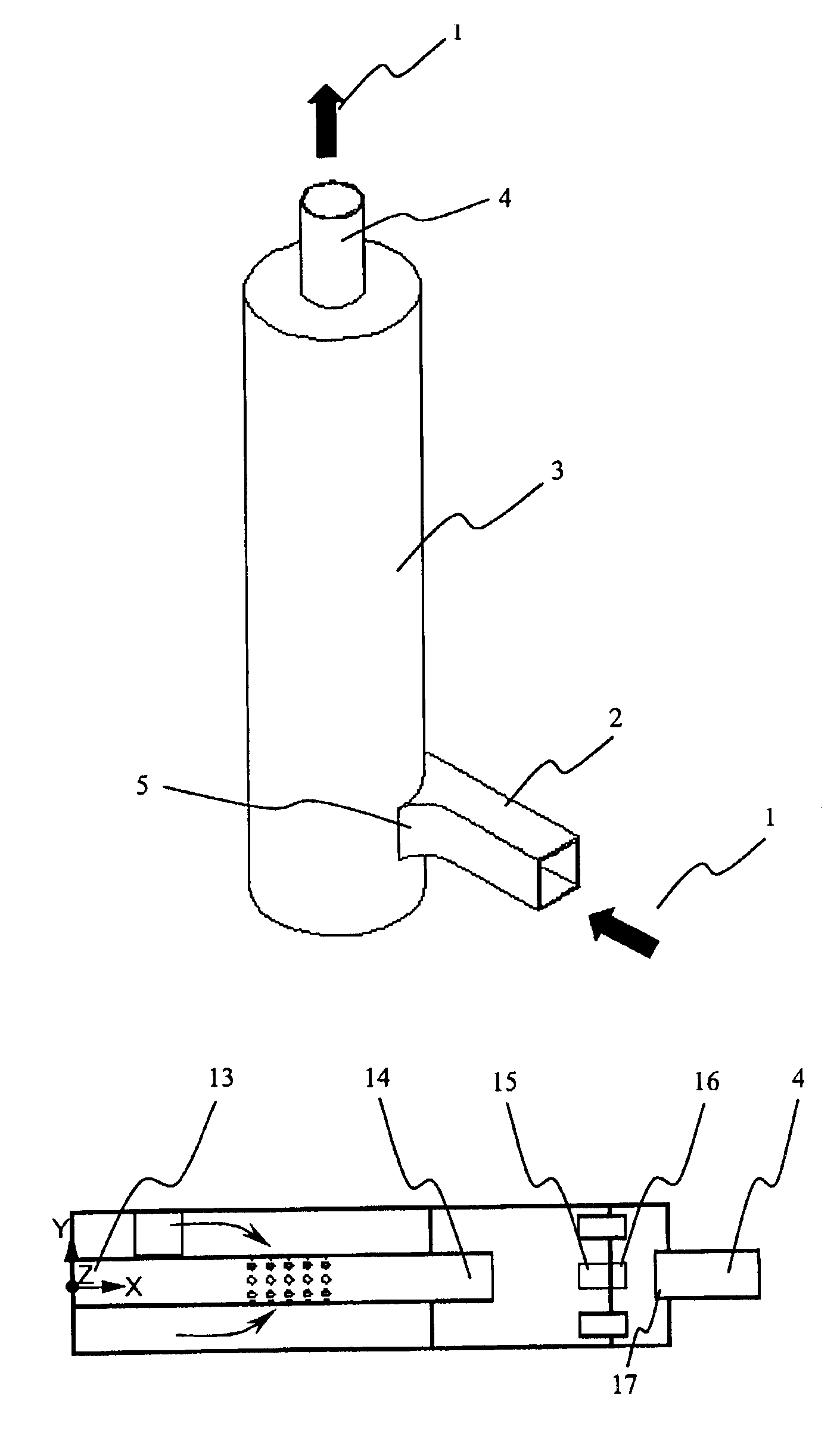
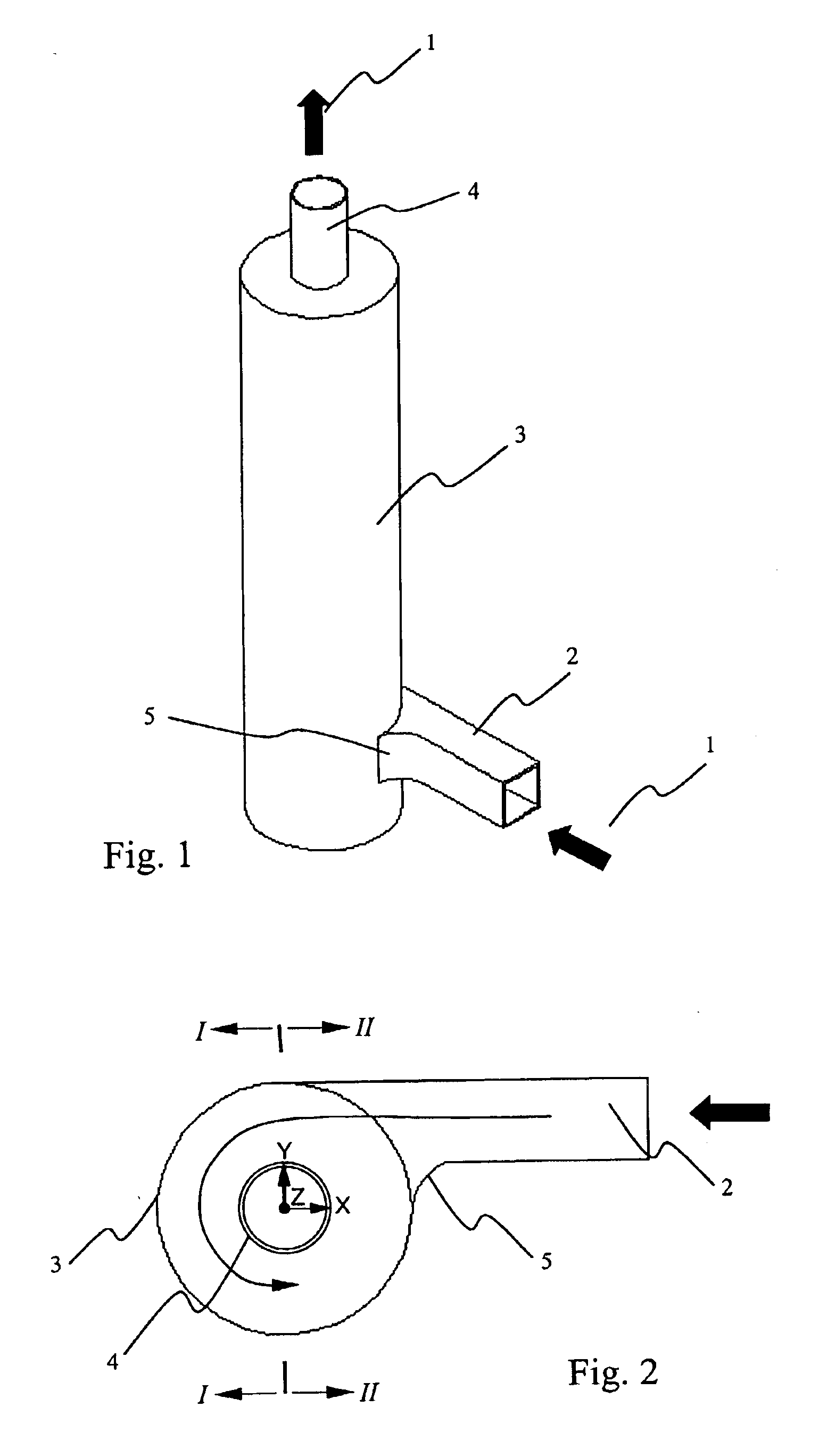
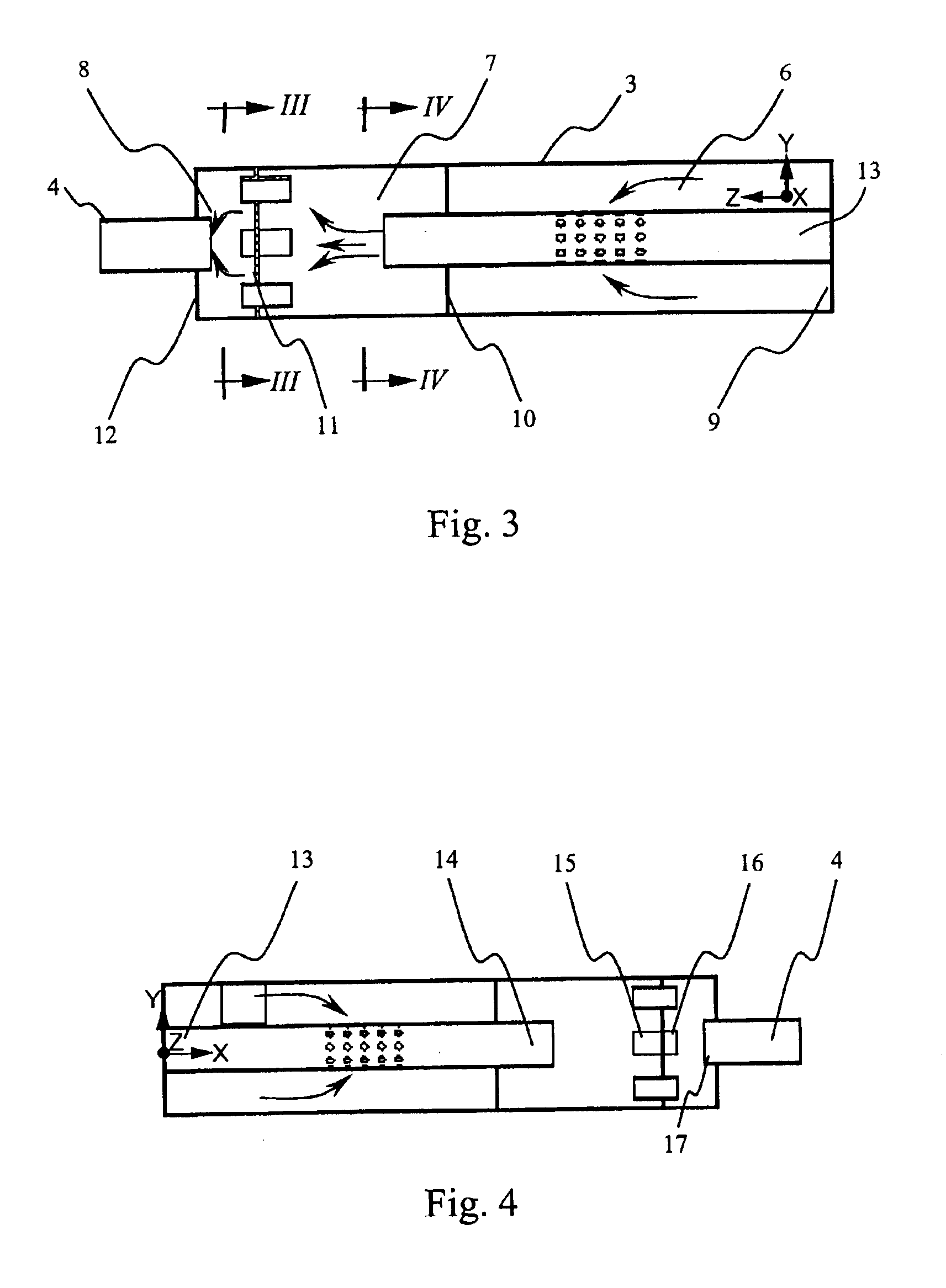
[0022]The muffler in accordance with the present invention is referred to as a reactive muffler. The reactive muffler uses an impedance mismatch along the path of sound wave propagation to reflect acoustic wave energy back to its source. As described below, the reactive muffler includes plural acoustic expansion chambers and pipes that function as acoustic resonators. These acoustic resonators correspond to annular sections (chambers) formed by the muffler casing and connecting pipes. Each acoustic resonator modifies the acoustic impedance along the sound transmission path in the muffler at its resonant frequencies. In general, the chamber lengths and pipe lengths are tuned to the major and harmonic frequencies in the appropriate exhaust noise frequency spectrum.

[0023]The following description is directed to an example muffler application to an internal combustion engine in which noise associated with exhaust gas from that engine is attenuated by the muffler. However, the present in...


PUM


Abstract

A high performance muffler, e.g., for an internal combustion engine, reduces exhaust or other gas noise while maintaining a low backpressure to prevent engine power loss. A side inlet pipe connects gas to a muffler body. The inlet pipe is flared at its connection to the muffler body to direct flow of the gas through an inlet chamber of the muffler in a spiral path. In an example embodiment, the muffler body includes three chambers separated by panels. An inlet expansion chamber is adjacent to the inlet and includes a first pipe with a perforated portion. An intermediate expansion chamber adjacent to the inlet chamber receives the gas from the first pipe. Four small pipes at the exit end of the intermediate chamber extend into an outlet expansion chamber. The gas in the outlet expansion chamber exits the muffler body by an outlet pipe at the other end of the outlet expansion chamber. The muffler achieves a high sound reduction without increasing backpressure.

Description

FIELD OF THE INVENTION[0001]The present invention relates to a muffler that may advantageously he employed with an internal combustion engine or with any other machine that generates acoustic energy during operation. The muffler in accordance with the present invention reduces exhaust noise while maintaining a low backpressure to prevent engine power loss.BACKGROUND[0002]Exhaust noise is a dominant noise associated with an internal combustion engine. Mufflers control and modify the noise produced by exhaust from internal combustion engines. Better acoustic performance of exhaust and other gas mufflers is important for the automobile and other machine-related industries in order to meet community noise standards. Indeed, new regulations are almost continually being proposed which require ever more stringent noise standards.[0003]Some muffler systems use sound attenuating materials like glass fiber. But due to the debris or waste existing in the exhaust gas from internal combustion en...

Claims


Application Information

Patent Timeline
Patent Type & Authority Patents(United States)
IPC IPC(8): F01N1/08
CPCF01N1/087F01N1/089F01N2490/04F01N2470/10F01N2470/18F01N2470/02
Inventor CAI, CHAOCHENG, MINGHUNG, KIN CHEW
Owner AGENCY FOR SCI TECH & RES
Why Eureka
Try Eureka