Structures and methods for deploying electrode elements

a technology of electrode elements and structures, applied in the field of systems and methods for ablating myocardial tissue, can solve the problems of cardiac efficiency loss, impaired hemodynamics, and consequences, and achieve the effect of simplifying the creation of complex lesions patterns

Inactive Publication Date: 2005-05-17
EP TECH
View PDF49 Cites 130 Cited by
  • Summary
  • Abstract
  • Description
  • Claims
  • Application Information

AI Technical Summary

Benefits of technology

[0019]A principal objective of the invention is to provide improved structures and methodologies for deploying electrode elements in contact with tissue. In a preferred implementation, the structures and methodologies that embody features of the invention make possible the creation of long, thin lesion patterns in tissue for the treatment of, for example, heart conditions like atrial fibrillation or atrial flutter.
[0020]In achieving these objectives, the invention provides an electrode support structure comprising a guide body having at its distal end a flexible spline leg. The spline leg is flexed to define an arcuate shape to facilitate intimate contact against tissue. An electrode element is carried by the spline leg for movement along its axis. The structure includes a control element coupled to the electrode element. The control element remotely imparts force to move the electrode element along the axis of the spline leg. Therefore, in use, the physician can cause the electrode element to travel along a path that the spline leg defines, without otherwise changing the location of the guide body.

Problems solved by technology

Because of a loss of atrioventricular synchrony, these people also suffer the consequences of impaired hemodynamics and loss of cardiac efficiency.
They are more at risk of stroke and other thromboembolic complications because of loss of effective contraction and atrial stasis.
Still, the treatment is far from perfect.
Yet, these drugs often fail to maintain sinus rhythm in the patient.
However, many people are intolerant to such drugs.
Still, these pharmacologic remedies often do not remedy the subjective symptoms associated with an irregular heartbeat.
They also do not restore cardiac hemodynamics to normal and remove the risk of thromboembolism.
Yet, despite its considerable clinical success, the maze procedure is technically difficult to do.
It requires open heart surgery and is very expensive.
The task is made more difficult because heart chambers vary in size from individual to individual.

Method used


Image

  • Structures and methods for deploying electrode elements
  • Structures and methods for deploying electrode elements
  • Structures and methods for deploying electrode elements

Examples


Embodiment Construction

[0081]This Specification discloses multiple electrode structures that embody aspects the invention. This Specification also discloses tissue ablation systems and techniques using multiple temperature sensing elements that embody other aspects of the invention. The illustrated and preferred embodiments discuss these structures, systems, and techniques in the context of catheter-based cardiac ablation. That is because these structures, systems, and techniques are well suited for use in the field of cardiac ablation.

[0082]Still, it should be appreciated that the invention is applicable for use in other tissue ablation applications. For example, the various aspects of the invention have application in procedures for ablating tissue in the prostrate, brain, gall bladder, uterus, and other regions of the body, using systems that are not necessarily catheter-based.

I. Loop Support Structures for Multiple Electrodes

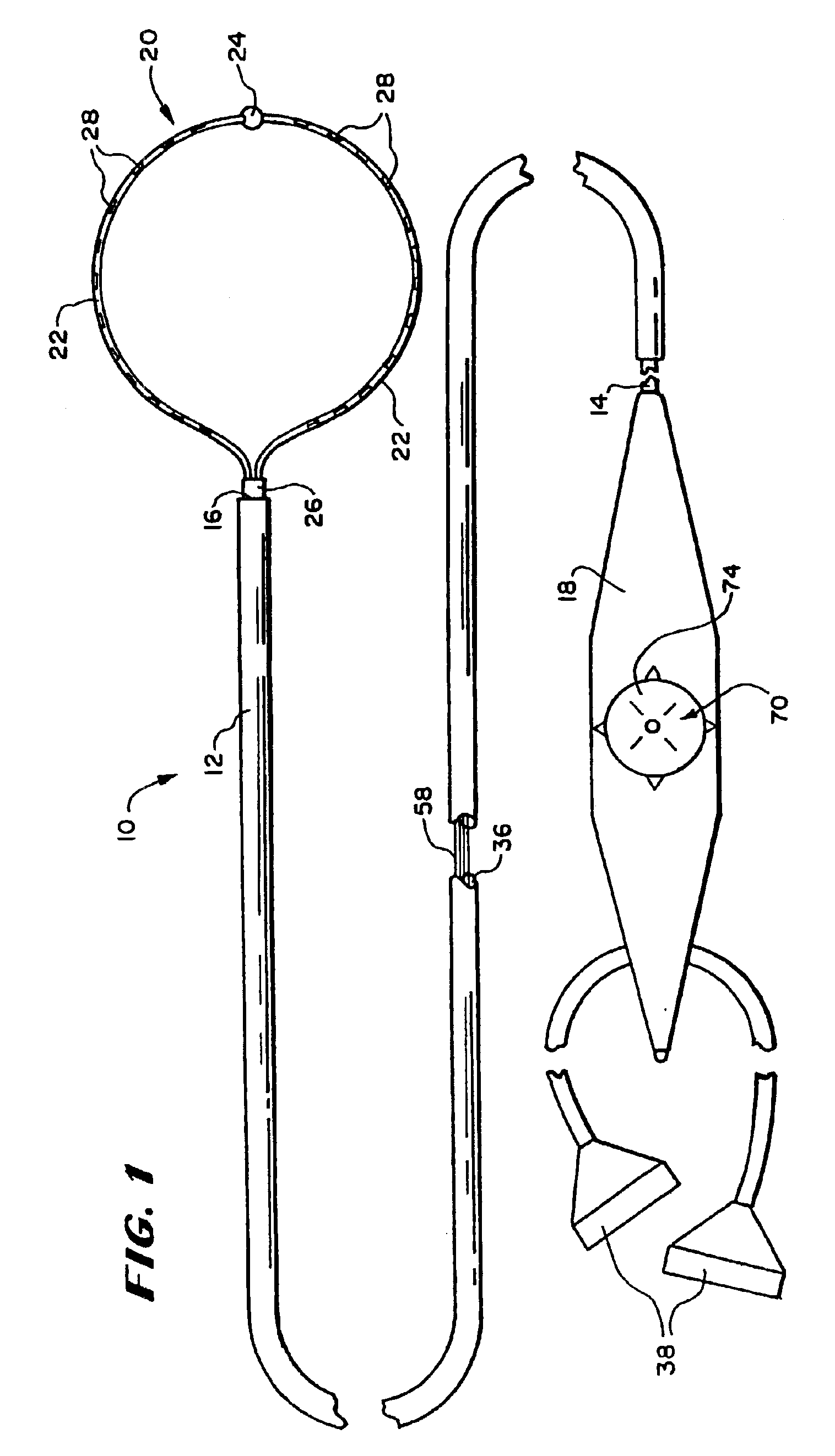
[0083]FIG. 1 shows a multiple electrode probe 10 that includes a loop structu...


PUM

PropertyMeasurementUnit
lengthaaaaaaaaaa
lengthsaaaaaaaaaa
lengthaaaaaaaaaa

Abstract

An electrode support structure comprises a guide body having at its distal end a flexible spline leg. The spline leg is flexed to define an arcuate shape to facilitate intimate contact against tissue. An electrode element is carried by the spline leg for movement along its axis. The structure includes a control element coupled to the electrode element. The control element remotely imparts force to move the electrode element along the axis of the spline leg. Therefore, in use, the physician can cause the electrode element to travel along a path that the spline leg defines, without otherwise changing the location of the guide body.

Description

CROSS-REFERENCE TO RELATED APPLICATIONS[0001]This application is a continuation of application Ser. No. 09 / 795,627, filed Feb. 28, 2001, now U.S. Pat. No. 6,544,262 which is a continuation of application Ser. No. 09 / 524,080, filed Mar. 13, 2000, now U.S. Pat. No. 6,214,002, which is a continuation of application Ser. No. 09 / 205,058, filed Dec. 3, 1998, now U.S. Pat. No. 6,071,282, which is a continuation of application Ser. No. 08 / 321,424, filed Oct. 11, 1994, now U.S. Pat. No. 5,885,278, which is a continuation in part of application Ser. No. 08 / 320,198, filed Oct. 7, 1994, now abandoned.FIELD OF THE INVENTION[0002]The invention relates to systems and methods for ablating myocardial tissue for the treatment of cardiac conditions.BACKGROUND OF THE INVENTION[0003]Normal sinus rhythm of the heart begins with the sinoatrial node (or “SA node”) generating an electrical impulse. The impulse usually propagates uniformly across the right and left atria and the atrial septum to the atrioven...

Claims


Application Information

Patent Timeline
Patent Type & Authority Patents(United States)
IPC IPC(8): A61B18/14A61N1/05A61B17/28
CPCA61B18/1492A61N1/056A61B18/1815A61B2017/2911A61B2018/00083A61B2018/00148A61B2018/00916A61B2018/00946A61B2018/00952A61B2018/1407A61B2018/142A61B2018/00214
Inventor FLEISCHMAN, SIDNEY D.
Owner EP TECH
Why Eureka
Try Eureka