Plasma reactor having a symmetric parallel conductor coil antenna

Inactive Publication Date: 2005-05-17
APPLIED MATERIALS INC
View PDF57 Cites 53 Cited by
  • Summary
  • Abstract
  • Description
  • Claims
  • Application Information

AI Technical Summary

Benefits of technology

[0015]The lateral displacements of the first plurality of conductors of the outer antenna preferably are uniform and the lateral displacements of the second plurality of conductors of the inner antenna preferably are uniform, whereby the inner a

Problems solved by technology

One problem with such a coil antenna is that there is a relatively large voltage drop across the coil antenna, which can induce unfavorable effects in the plasma such as arcing.
Unfortunately, at such lower frequencies, the coupling of RF power to the plasma can be less efficient.
Another disadvantage of operating at the lower frequency range (e.g., 2 MHz) is that the component size of such elements as the impedance match network are much larger and therefore more cumbersome and costly.
Another problem with coil antennas is that efficient inductive coupling to the plasma is generally achieved by increasing the number of turns in the coil which creates a larger magnetic flux density.
This in turn leads to instabilities and difficulties in maintaining an impedance match over varying chamber conditions.
One limitation of coil antennas overlying the chamber ceiling (both conventional as well as the interleaved type) is that the mutual inductance between adjacent conductors in the antenna is generally in a horizontal direction generally orthogonal from the vertical direction in which RF power must be inductively coupled to the plasma.
This is one important factor that limits the spatial control of the power deposition to the plasma.
Thus, the ability to chan

Method used


Image

  • Plasma reactor having a symmetric parallel conductor coil antenna
  • Plasma reactor having a symmetric parallel conductor coil antenna
  • Plasma reactor having a symmetric parallel conductor coil antenna

Examples


first integrated embodiment

[0054]

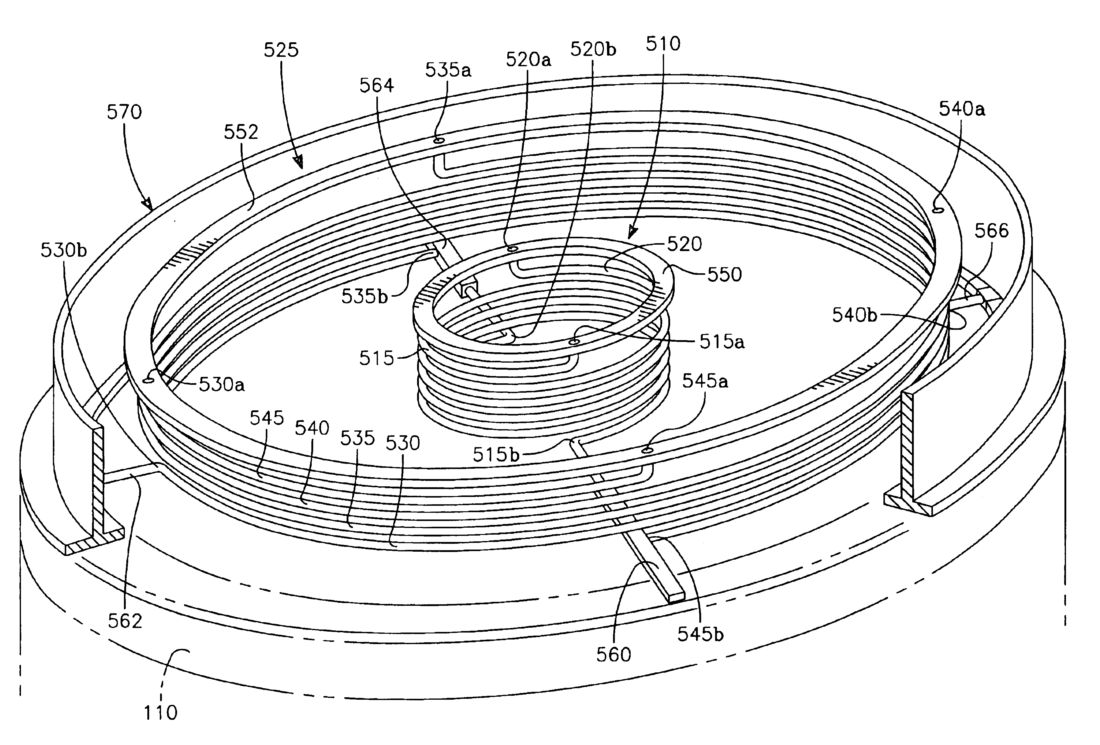
[0055]FIG. 5 illustrates a first integrated embodiment having multiple solenoidal overhead antennas, each having a plurality of interleaved conductors. An inner solenoidal antenna 510 has a pair of interleaved conductors 515, 520 with power taps 515a, 520a at 180 intervals. An outer solenoidal antenna 525 has four interleaved conductors 530, 535, 540, 545 with power taps 530a, 535a, 540a, 545a at 90 degree intervals with respect to the axis of symmetry. Each interleaved conductor is generally parallel to the remaining conductors of a given antenna. An inner circular power bus 550 overlying the inner antenna 510 is connected to the inner antenna power taps 515a, 520a. Similarly, an outer circular power bus 552 overlying the outer antenna 525 is connected to the outer antenna power taps 530a, 535a, 540a, 545a. A set of four arms 560, 562, 564, 566 underlying the outer antenna 525 and disposed at 90 degree intervals connect respective ground taps to a circular grounded housing 57...


PUM

PropertyMeasurementUnit
Thicknessaaaaaaaaaa
Lengthaaaaaaaaaa
Shapeaaaaaaaaaa

Abstract

The invention in one embodiment is realized in a plasma reactor for processing a semiconductor workpiece. The reactor includes a vacuum chamber having a side wall and a ceiling, a workpiece support pedestal within the chamber and generally facing the ceiling, a gas inlet capable of supplying a process gas into the chamber and a solenoidal interleaved parallel conductor coil antenna overlying the ceiling and including a first plurality conductors wound about an axis of symmetry generally perpendicular to the ceiling in respective concentric helical solenoids of at least nearly uniform lateral displacements from the axis of symmetry, each helical solenoid being offset from the other helical solenoids in a direction parallel to the axis of symmetry. An RF plasma source power supply is connected across each of the plural conductors.

Description

CROSS REFERENCE TO RELATED APPLICATIONS[0001]This is a divisional of U.S. application Ser. No. 09 / 611,169, filed Jul. 6, 2000, now U.S. Pat. No. 6,685,798, entitled “A PLASMA REACTOR HAVING A SYMMETRICAL PARALLEL CONDUCTOR COIL ANTENNA”, by John Holland, et al. and assigned to the present assignee.[0002]The following application / patents contain subject matter related to the present invention:[0003]U.S. patent application Ser. No. 09 / 611,170, filed Jul. 6, 2000, entitled “A PLASMA REACTOR HAVING A SYMMETRIC PARALLEL CONDUCTOR COIL ANTENNA”, by John Holland, et al.; U.S. Pat. No. 6,409,933, issued Jun. 25, 2002, entitled “A PLASMA REACTOR HAVING A SYMMETRICAL PARALLEL CONDUCTOR COIL ANTENNA”, by John Holland, et al.; U.S. Pat. No. 6,414,648, issued Jun. 11, 2002, entitled “A PLASMA REACTOR HAVING A SYMMETRICAL PARALLEL CONDUCTOR COIL ANTENNA”, by John Holland, et al.; U.S. Pat. No. 6,462,481, issued Oct. 8, 2002, entitled “A PLASMA REACTOR HAVING A SYMMETRIC PARALLEL CONDUCTOR COIL AN...

Claims


Application Information

Patent Timeline
IPC IPC(8): H01J37/32
CPCH01J37/321
Inventor HOLLAND, JOHNTODOROW, VALENTIN N.BARNES, MICHAEL
Owner APPLIED MATERIALS INC
Why Eureka
Try Eureka