
Passive transponder identification and credit-card type transponder

a transponder identification and credit card technology, applied in the direction of differential interacting antenna combinations, instruments, mechanical actuation of burglar alarms, etc., can solve the problems of undesired data information to be radiated, unusable identification system, and requiring very sophisticated shielding capabilities, so as to reduce the drifting effect of transmitting frequency, increase system bandwidth, and reduce the effect of reducing the efficiency of said transponder

Inactive Publication Date: 2005-05-17
CREDIPASS
View PDF6 Cites 51 Cited by
  • Summary
  • Abstract
  • Description
  • Claims
  • Application Information

AI Technical Summary

Benefits of technology

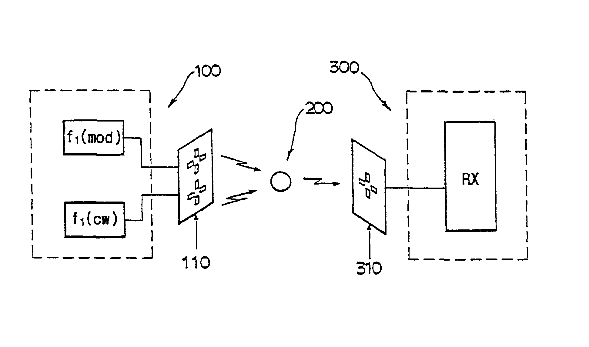
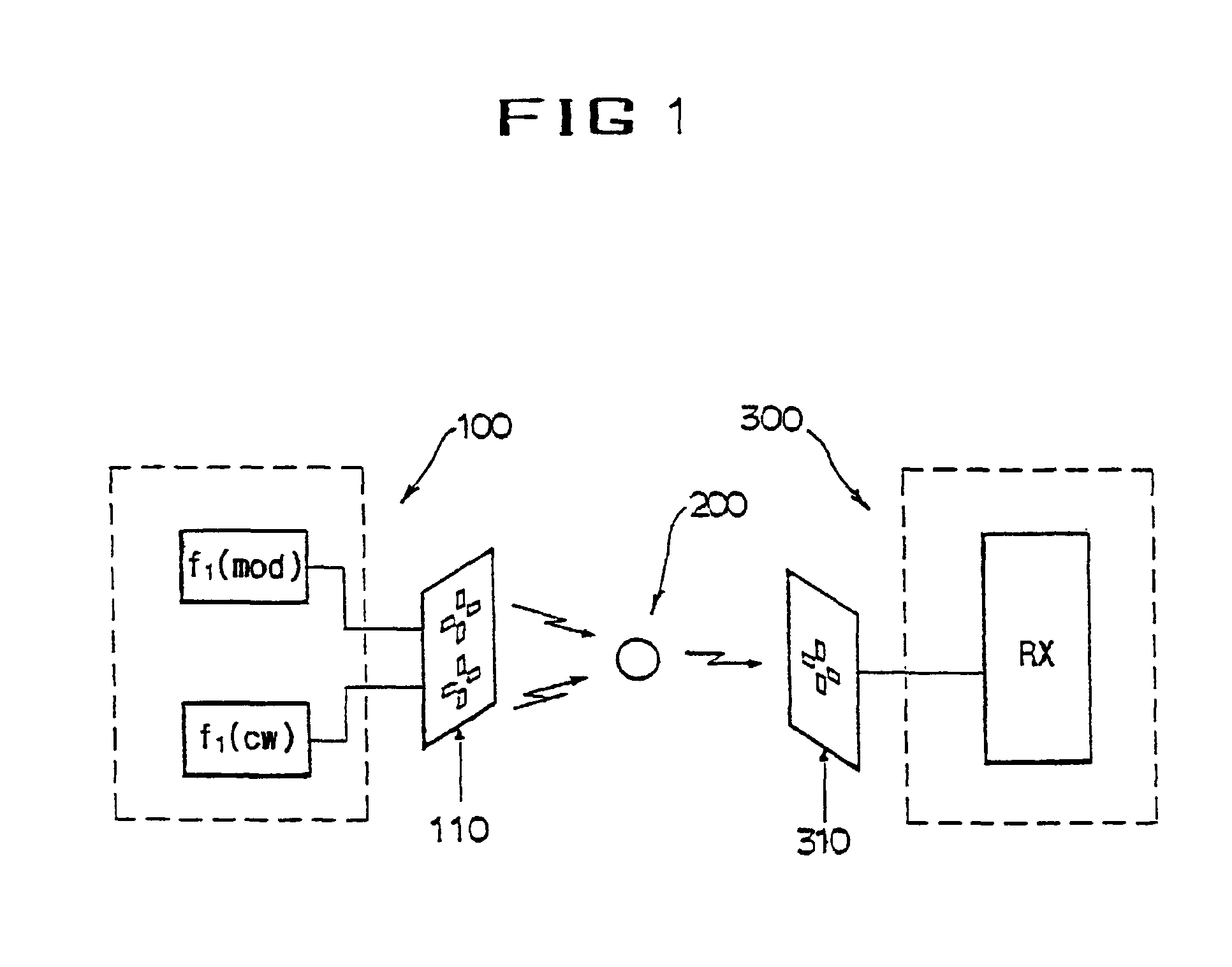
[0015]Further, the first transmitter generates tone-modulated high frequency biased or polarized to one side of the center frequency while the second transmitter generates continuous wave(CW) high frequency polarized to the other side of the center frequency. Such both signals are independently and suddenly turned to dipole antenna strips perpendicular to each other arranged to cover desired area. The said dipole strips are aligned at a right angle to each side at individual frequencies, and, at the same frequency, positioned perpendicular to the opposite side. Therefore, it is resulted that cross-polarized transmission is successfully performed at both frequencies within the requisite detection area.
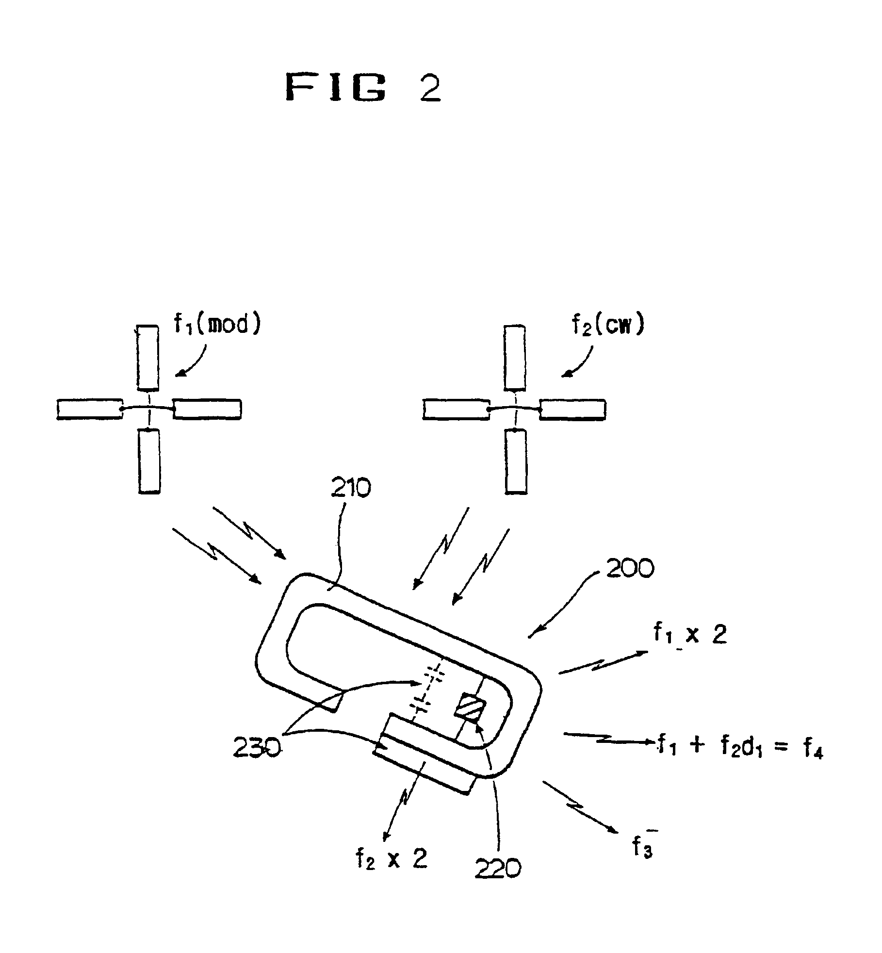
[0022]The tone-modulated signal f1 controls the occurrence of stationary wave causing blind spot within an area detected by the passive transponder 200.
[0031]It is more important that an operation method to use both frequencies can reduce drifting effect of a transmitting frequency and increase bandwidth of the system in the efficiency aspect of the transponder for re-radiating an incident HF signal of a Back scatter. Particularly, the frequency tuned with antenna 210 of the transponder 200 can be present in any location between two frequencies transmitted without excessive reduction of the efficiency of said transponder; thus, it needs no use of accurate antenna to be manufactured while problems relating non-tuning could be reduced to a minimum. In this regard, common tuning point of the transponder 200 is polarized toward the lower side of two frequencies due to dielectric loading effect of any object adjacent to the transponder. For example, if it was re-tuned downward the selected center frequency of said antenna of the transponder 200, it could increase the efficiency of the transponder 200 relative to any transmitting frequency lower than it. The entire mixer is not seriously influenced by this condition because the desired mixing performance is developed by 10 or more of HF power ratio. Therefore, the drifting effect of the transmitter is minimized by such manner described above. In other words, unlikely the harmonics re-radiated in a single frequency system, the shift in frequency of the transmitter is not multiplied and the drift at one frequency can be offset by the opposite shift of the other transmitter.

Problems solved by technology

Such identification system has a shortage of practically not used due to occurrence of reading error at responding to sensitivity and different conditions to ensure detection of transponder within detection area.
However, the filter has a problem of causing even small frequency shift of the transmitted signals to easily serve as re-radiation frequency present outside of the filter pass-band, thus requiring very sophisticated shielding capability.
While these harmonic signals easily transmitting to the outside cause undesired data information to be radiated from any transponder beyond the detection area.
Consequently, HF energy which transmits by unexpected reflection such as multi-stationary wave is not effective to accomplish the original purpose of the system.
On the contrary, if insufficient amount of energy is received or re-radiated by harmonics, the system may not respond even the transponder element being actually present, within the detection area.
Also, in case the transponder coming close to human body or metallic objects, it deflects tuning of a resonant tank circuit to result the dissipation of HF energy required by receiver.
However, even though power consumed in the detection area is important to form electro-statistic field required within the detection area, such field may be unfortunately prevented from the transponder by conductor enclosing it or conversed from the transponder by traffic signs made of metallic materials or other metal structures around.
In addition, LF field is likely to be under reading error or immobile condition at long distance by nearby metal structures.

Method used


Image

  • Passive transponder identification and credit-card type transponder
  • Passive transponder identification and credit-card type transponder
  • Passive transponder identification and credit-card type transponder

Examples


example 1

[Example 1]

[0057]In this example as an embodiment of the present invention, a credit card type transponder is equipped with RF Remote Identification System (“RFID”) using RF to identify at long distance.

[0058]More particularly, the system utilizes the open area of a micro-strip antenna to a maximum and accomplishes the greatest radiation efficiency by properly arranging two slots and two dipole antennas and matching the resonant point relative to the secondary harmonics of the received wave; and receives beam power radiated from an interrogator to the highest degree within a small size of card so that it can eliminates the low efficiency problem of conventional system which uses Back Scatter having the same transmitting / receiving frequencies as its carrier; characterized in that it consists of dual-polarization antenna formed by arranging said two slot resonant antennas perpendicular to each other to constantly manage the accepted power dependent on the direction of antennas and to ...

example 2

[Example 2]

[0087]In this example as another embodiment of the present invention, an electronic fare collection system for driving automobiles such as toll road charging system (referring hereinafter “charging system”) using a remote RFID built-in credit card (referring hereinafter “RFID credit card”) prepared by Example 1.

[0088]FIG. 13 illustrates a systematic drawing of the charging system using RFID credit card 10, the charging system being consisted of an interrogator 40 to directly identify the RFID credit card 10 placed within the driving automobile without any kind of automobile loading means; a detector 44 to detect and sort type of the automobile; a video system 45 to photograph plate number of illegally passing car; and an identification and control computer 41 to identify the RFID credit card of the automobile passing the tollgate. The system further includes a known management computer 42 to collect fare to receive data transmitted by the identification computer 41, a cen...


PUM


Abstract

A passive transponder identification system and credit card type transponder are disclosed, particularly, the transponder identification system to utilize a transmitting manner of two different RF signals is provided. The present invention directly relates to a passive transponder without any kind of power source. Therefore, the present invention has advantages of having a constant gain value by developing a high-gain dual polarizing antenna for a small credit card type passive transponder to identify at long distance, independently to any direction of the transponder; improving gain values than conventional transponder tag antenna by 6-9 dB to ensure a sub-permanent life time by providing the desired identification performance by a small credit card type passive transponder without power supply; and being applicable to any systems to identify and distinguish high-speed moving objects.

Description

FIELD OF THE INVENTION[0001]The present invention relates to a passive transponder identification system operated by storage of information and transmission of inherent number and a credit card type transponder, and more particularly, to a radio frequency(“RF”) passive transponder useful in ID proximity card, pass card for bus or subway, and the like, which should recognize or identify at close distance, simultaneously with IC card.BACKGROUND OF THE RELATED ART[0002]Such system requires remote-control transponder installed with subminiature transmitter-receiver circuits capable of being carried in any moving objects therein. Particularly, the present invention provides a passive transponder to identification technique at relatively long range and high-speed driving objects.[0003]Conventional transponder identification system transmits a single radio frequency to detect by antenna such as transponder tag, and non-linear impedance of semiconductor diode used for this generates selecti...

Claims


Application Information

Patent Timeline
Patent Type & Authority Patents(United States)
IPC IPC(8): G06K19/07G06K19/077G06K7/00B42D15/10G06K17/00G06K19/00H01Q5/10H01Q9/26H01Q9/28H01Q13/10H01Q21/29H01Q21/30H04B1/59
CPCG06K7/0008G06K7/10316G06K19/07749G06K19/0724G06K19/0723
Inventor KIM, JI-TAEJEONG, DONG-SEOG
Owner CREDIPASS
Learn More