

Instrument setup system for a fluorescence analyzer
a fluorescence analyzer and instrument setup technology, applied in the field of flow or scanning cytometry, can solve the problems of compensation, no longer applicable to current instrument settings, and inability to measure dye fluorescence independently
- Summary
- Abstract
- Description
- Claims
- Application Information
AI Technical Summary
Benefits of technology
Problems solved by technology
Method used
Image

Examples
example 1
Flow Cytometer Setup
[0136]The present example describes setup of a flow cytometry system according to the present invention.
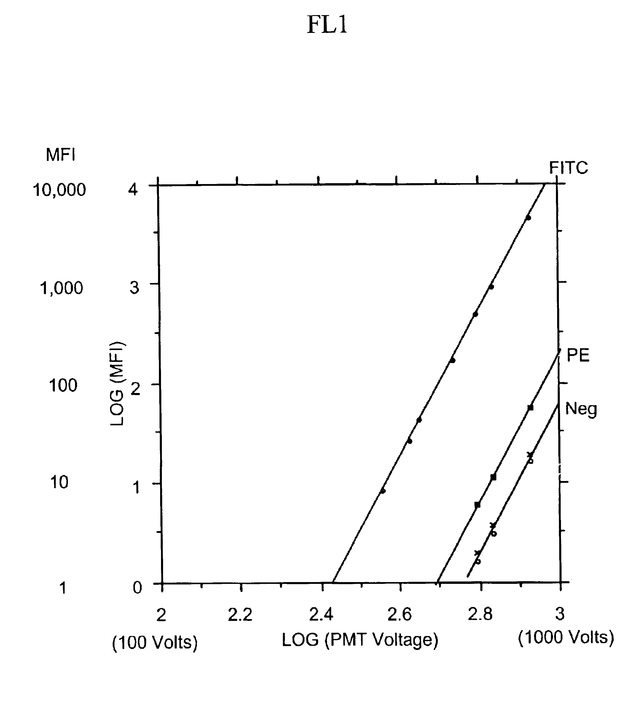
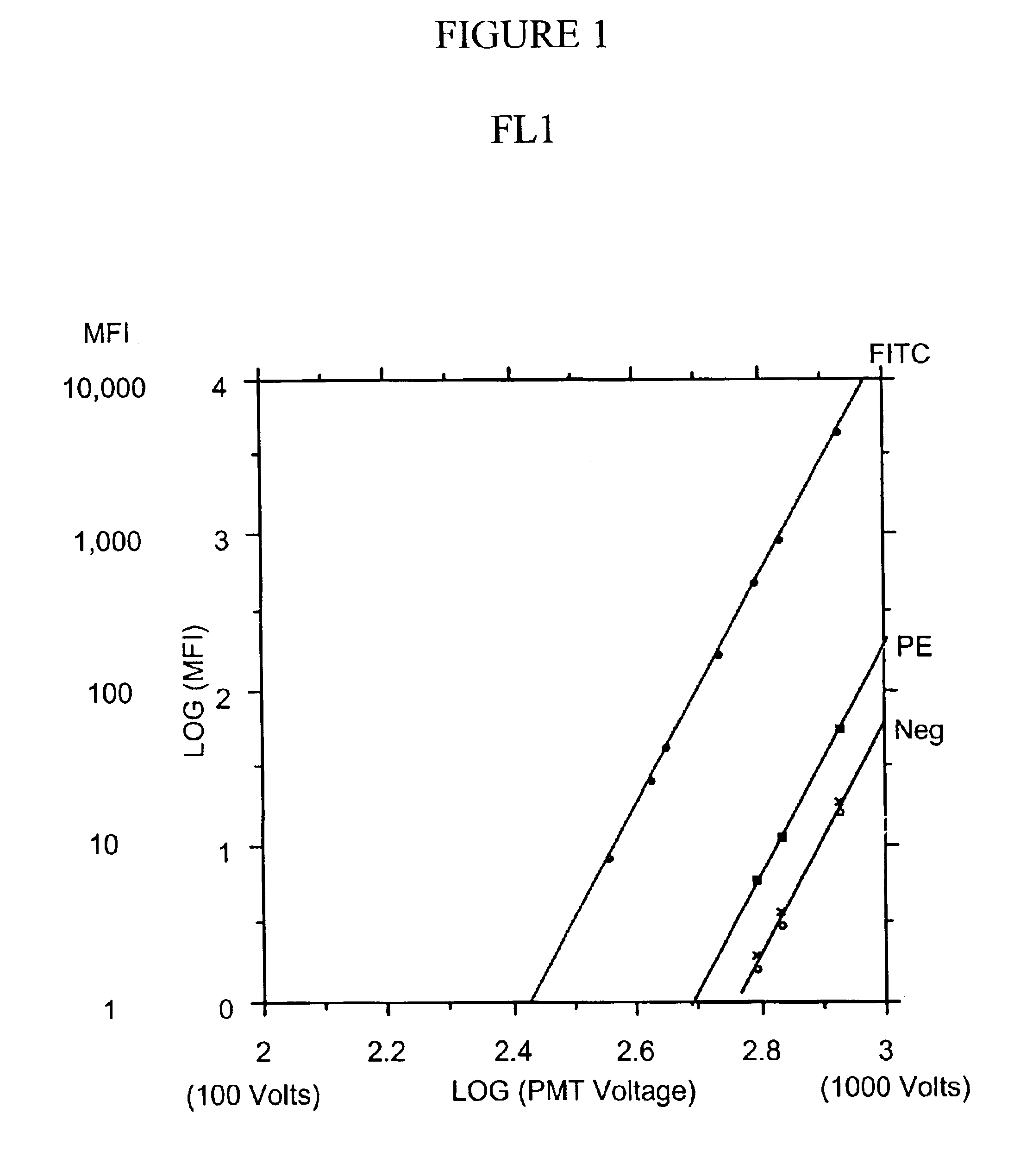
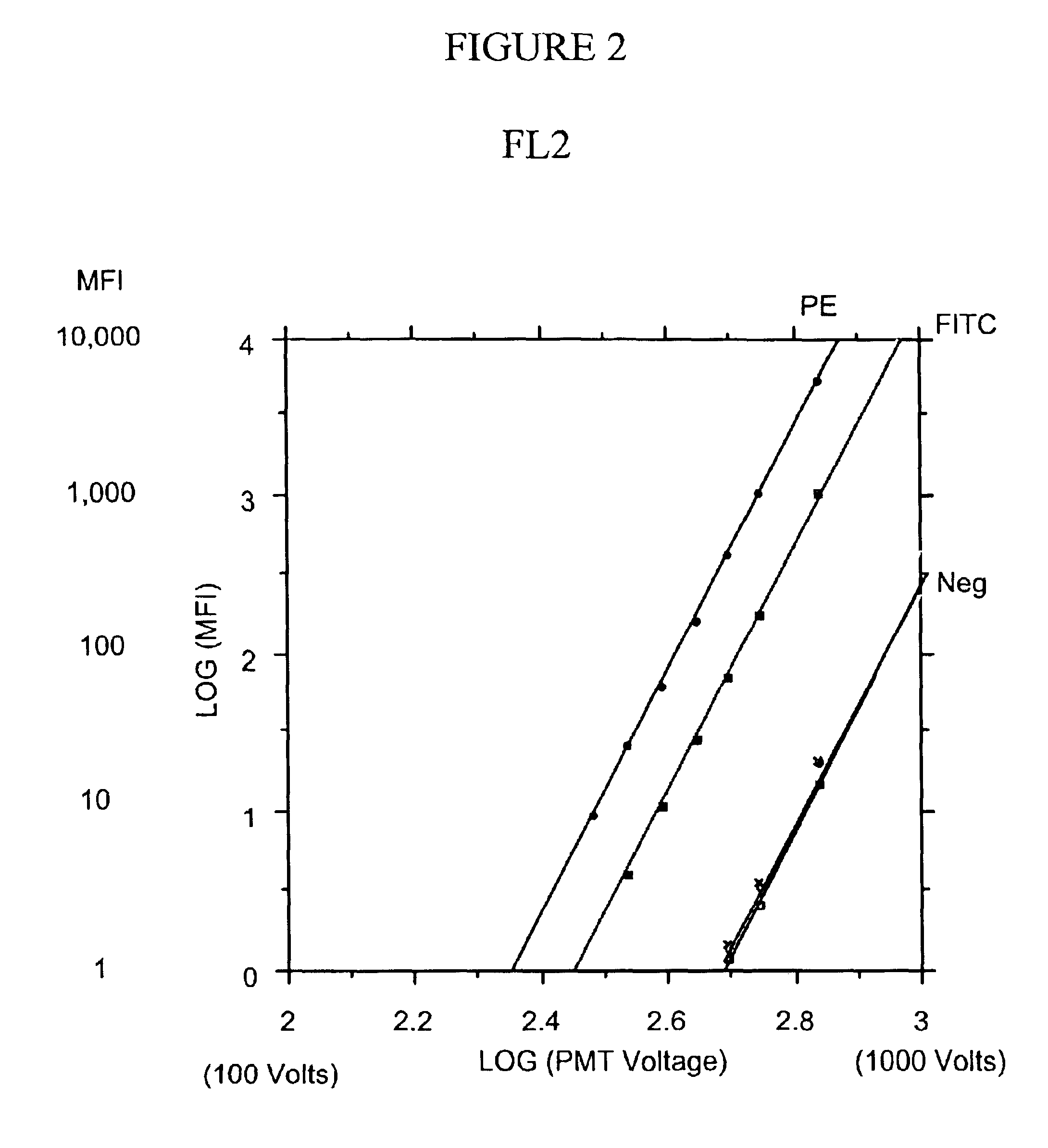
[0137]A flow cytometer according to the present invention was simulated using a BD FACSCaliburm flow cytometer (BD Biosciences, San Jose, Calif.) with the four-color fluorescence detection option. This cytometer has two lasers, a blue laser (488 nm) and a red diode laser (˜635 nm). Photomultiplier tubes (PMT) are used for measurement of dye fluorescence. The wavelength ranges detected for the measurement of forward scatter (FSC) and side scatter (SSC), and in each of the fluorescence detection channels (FL1-FL4), are shown in the table, below.
[0138]
ChannelWavelength RangeFSC488 / 10 nmSSC488 / 10 nmEL1530 / 30 nmFL2585 / 42 nmFL3 ≧670 nmFL4661 / 16
[0139]The detectors are intended to detect fluorescence from the following dyes as the primary dyes.
[0140]
DetectorDyeDye AbbreviationFL1fluorescein isothiocyanateFITCFL2phycoerythrinPEFL3peridinin chlorophyll proteinPerC...
example 2
Setup Adjustments and Optimization
[0175]The previous example describes the setup of a flow cytometer of the present invention. During instrument setup, voltages are set to provide fluorescence intensity measurements within a desired range, and the compensation matrix is derived to provide correct compensation. However, the user may modify the instrument setup further by either direct or indirect adjustment of the PMT voltages, or by adjustment of either the spillover matrix or compensation matrix. As described in this example, the present invention enables adjustments to the instrument setup to be made without the need for additional samples to be run.
Indirect Adjustment of PMT Voltages
[0176]A preferred feature enabled by the present invention is the ability to automatically readjust the instrument setup such that the data from the analysis of a population are displayed within a desired region of the dataspace. In a preferred embodiment, this feature is implemented such that the use...
example 3
Quantitation
[0188]Using the system of Example 1, a quantitative measure of the amount of dye on a particle will be proportional to the measured fluorescence of the dye after removing the contribution from autofluorescence. Typically, the relationship between the amount of dye and the fluorescence is estimated empirically by first measuring a series of quantitation standards having different, known amounts of dye, thus obtaining an estimate of fluorescence as a function of the amount of dye. In this case, the fluorescence is proportional to the amount of dye, i.e.,
fluorescence=α·dye,
where α is the proportionality constant. The amount of dye as a function of fluorescence is obtained as the inverse of the function describing fluorescence as a function of the amount of dye. Thus,
dye=(1 / α)·flourescence.
[0189]The relationship between the amount of dye and the fluorescence measured using an initial PMT voltage is adjusted following a change in PMT voltage using the brightness ratio. The br...
PUM
 Abstract
Description
Claims
Application Information