

Display device having resin black matrix over counter substrate
a liquid crystal display and resin technology, applied in semiconductor devices, instruments, optics, etc., can solve the problems of negligible black matrix capacitance of interlayer insulating films, etc., and achieve the effect of improving bonding accuracy and reducing overlap width
- Summary
- Abstract
- Description
- Claims
- Application Information
AI Technical Summary
Benefits of technology
Problems solved by technology
Method used
Image

Examples
embodiment 1
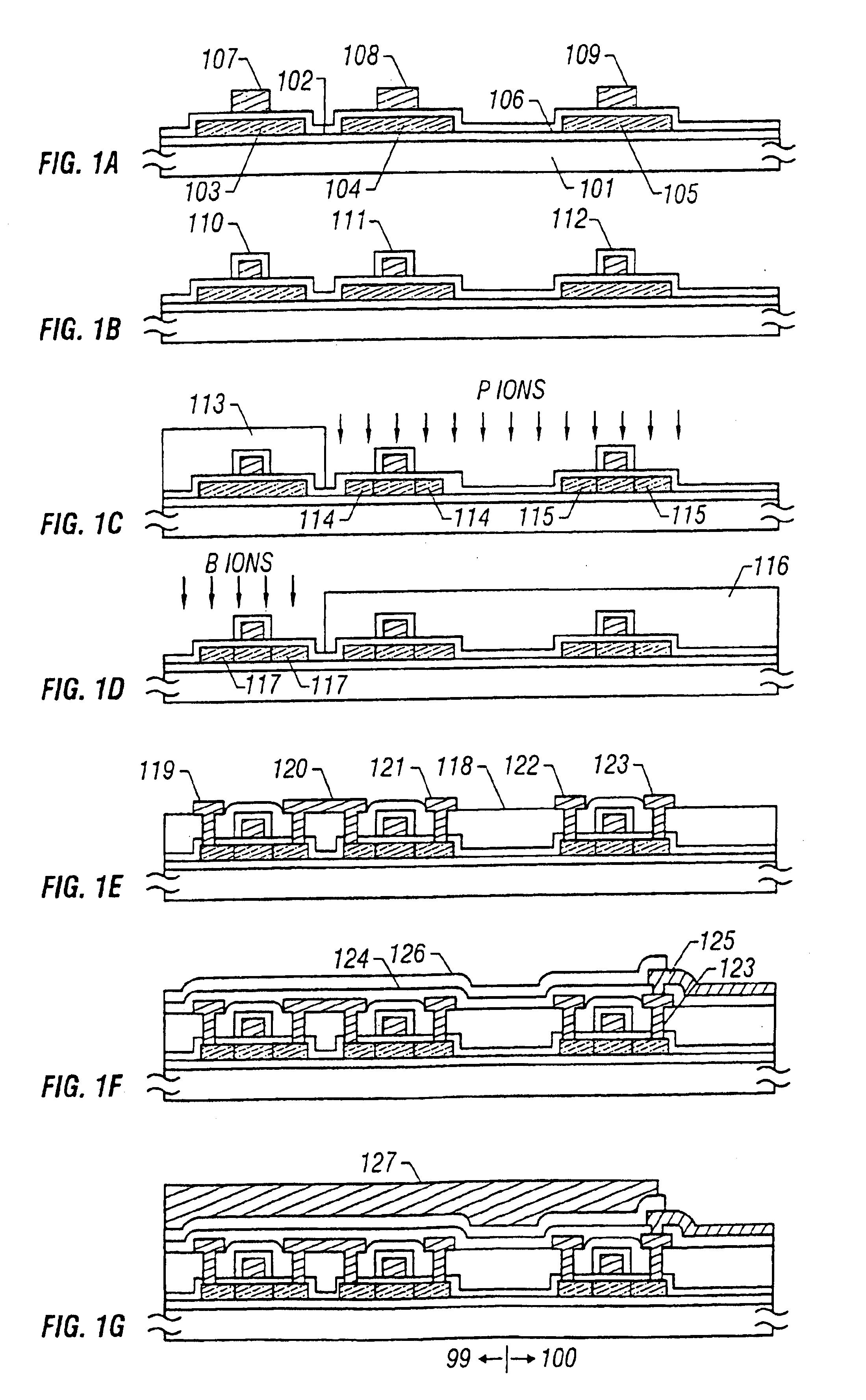
[0055]Referring to FIGS. 1A-1G, a description is made of a manufacturing process of a monolithic active matrix circuit according to a first embodiment of the invention. This is a low-temperature polysilicon process. In FIGS. 1A-1G, the left side shows a manufacturing process of TFTs 99 of a driver circuit and the right side shows a manufacturing process of a TFT 100 of an active matrix circuit.
[0056]First, a silicon oxide film of 1,000-3,000 Å in thickness, i.e., an undercoat oxide film 102 is formed on a glass substrate 101 (first insulating substrate) by sputtering or plasma CVD in an oxygen atmosphere.
[0057]Then, an amorphous silicon film having a thickness of 300-1,500 Å, preferably 500-1,000 Å, is formed by plasma CVD or LPCVD, and crystallized or improved in crystallinity by thermal annealing at a temperature not lower than 500° C., preferably 500-600° C. Optical annealing (for instance, laser annealing) may be performed after the thermal annealing to further improve the cryst...
embodiment 2
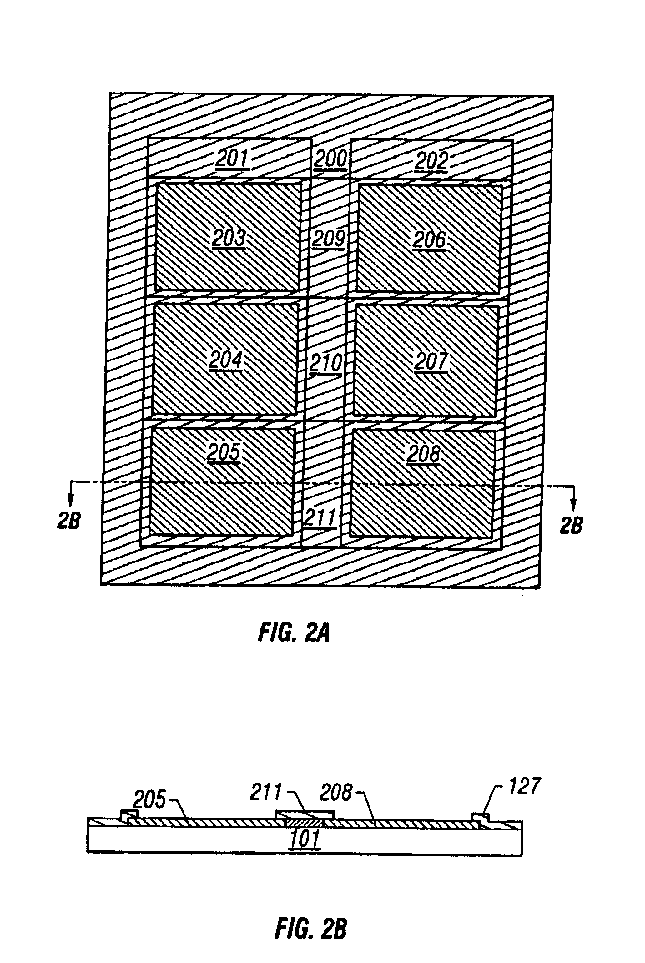
[0071]This embodiment is directed to the configuration of an integrated liquid crystal panel which is formed according to the manufacturing method of the first embodiment and in which six panels are unified. FIGS. 2A and 2B show a general configuration of an integrated liquid crystal panel according to this embodiment.
[0072]FIG. 2A is a plan view of the integrated liquid crystal panel and shows a general configuration of a substrate on which TFTs are formed. FIG. 2B is a sectional view taken along line A-A′ in FIG. 2A. FIGS. 2A and 2B show a state in which the resin black matrix 127 of the first embodiment is formed in peripheral driver circuits 201, 202 and 209-211.
[0073]In the peripheral driver circuits, because of a high degree of is integration, such defects as reduce the production yield occur at a high possibility. According to an empirical rule in forming an integrated circuit, the yield is lower in a peripheral portion of a substrate than in its central portion. This is cons...
embodiment 3
[0076]This embodiment is directed to a case where a planation film is provided on a substrate according to the second embodiment on which TFTs are formed. That is, a planation film 428 is provided in a pixel region and regions where a black matrix is formed.
[0077]FIGS. 3A and 3B show this embodiment in which the same reference numerals as in the second embodiment denote the same parts.
[0078]First, a substrate according to the second embodiment formed with TFTs are produced according to the manufacturing method of the first embodiment. FIGS. 4A-4G show a specific manufacturing process.
[0079]First, a silicon oxide film of 1,000-3,000 Å in thickness, i.e., an undercoat oxide film 402 is formed on a glass substrate 401 (first insulating substrate) through sputtering or plasma CVD in an oxygen atmosphere.
[0080]Then, an amorphous silicon film having a thickness of 300-1,500 Å, preferably 500-1,000 Å, is formed by plasma CVD or LPCVD, and crystallized or improved in crystallinity by therma...
PUM
 Abstract
Description
Claims
Application Information