Charged-particle beam exposure apparatus, charged-particle beam exposure method, control data determination method, and device manufacturing method using this method

a technology of charge-particle beam and charge-particle beam, which is applied in the field of charge-particle beam exposure apparatus and an exposure method therefor, can solve the problems of reducing the availability of electron beam drawing apparatus, requiring several hours to correct the approximate solution formula, and long calculation time, so as to achieve the effect of rapid correction of the proximity

Inactive Publication Date: 2005-06-07
CANON KK
View PDF7 Cites 12 Cited by
  • Summary
  • Abstract
  • Description
  • Claims
  • Application Information

AI Technical Summary

Benefits of technology

[0008]The present invention has been proposed to solve the conventional problems, and has as its object to provide a charged-particle beam exposure apparatus which can select a proper one of a plurality of pieces of correction exposure information in accordance with the conditions of a surface to be exposed, thereby rapidly performing proper proximity effect correction, and an exposure method therefor.
[0012]exposure means for controlling the dosage of the charged particle beam for each irradiation position on the basis of the data selected by the selection means, thereby exposing the member to be exposed with the pattern.

Problems solved by technology

The disadvantage is a long calculation time.
However, even the use of the approximate solution formulae requires several hours to correct the proximity effect for all direct writing LSI chips.
This occupies an electron beam drawing apparatus for several ten hours in order to only determine parameters, which decreases the availability of the electron beam drawing apparatus.

Method used


Image

  • Charged-particle beam exposure apparatus, charged-particle beam exposure method, control data determination method, and device manufacturing method using this method
  • Charged-particle beam exposure apparatus, charged-particle beam exposure method, control data determination method, and device manufacturing method using this method
  • Charged-particle beam exposure apparatus, charged-particle beam exposure method, control data determination method, and device manufacturing method using this method

Examples


Embodiment Construction

[0076]Preferred embodiments of the present invention will now be described in detail in accordance with the accompanying drawings.

[0077]The embodiments will explain an electron beam exposure apparatus as an example of the charged-particle beam exposure apparatus. However, the present invention is not limited to an electron beam exposure apparatus, but can also be applied to, e.g., an ion beam exposure apparatus.

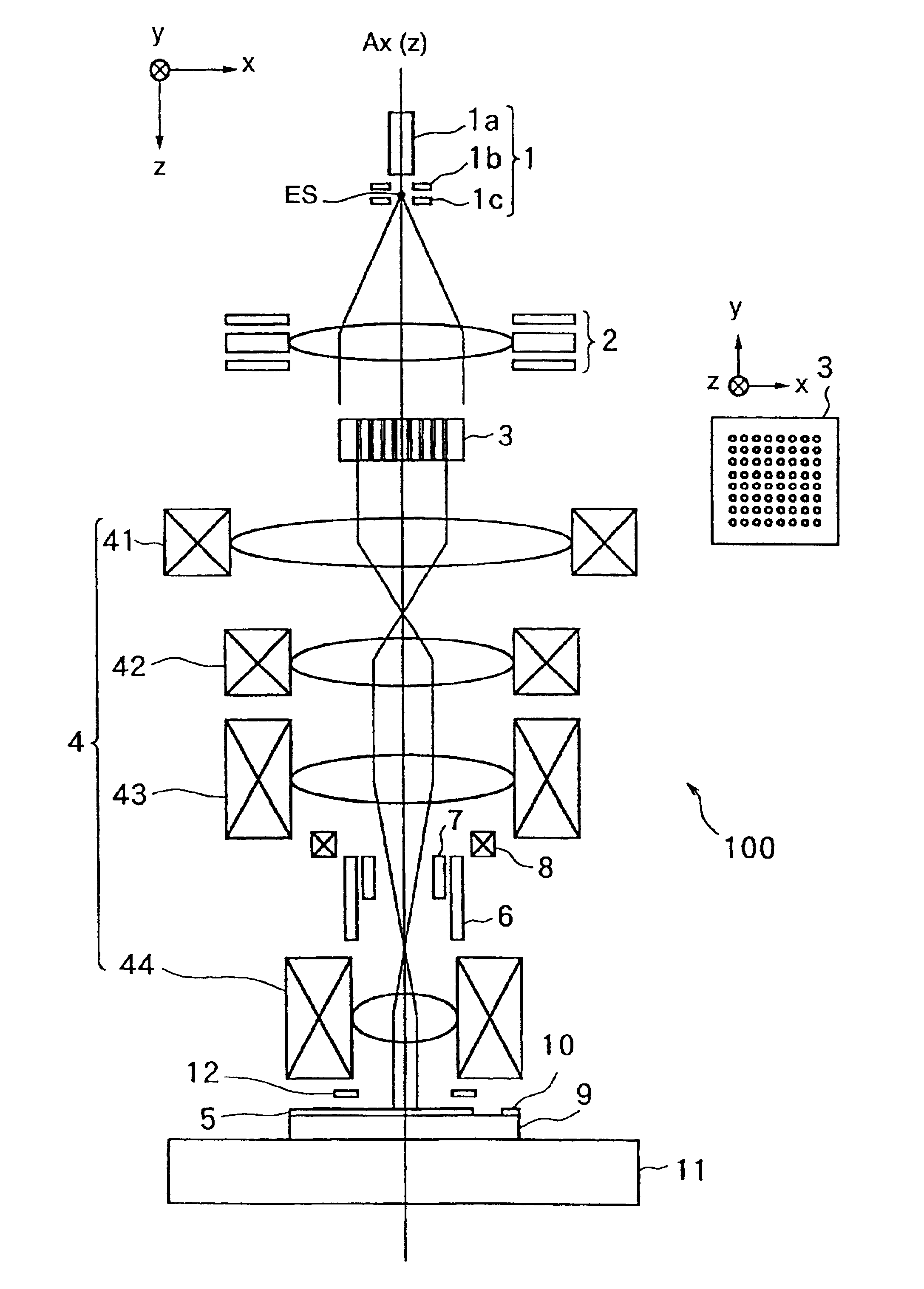
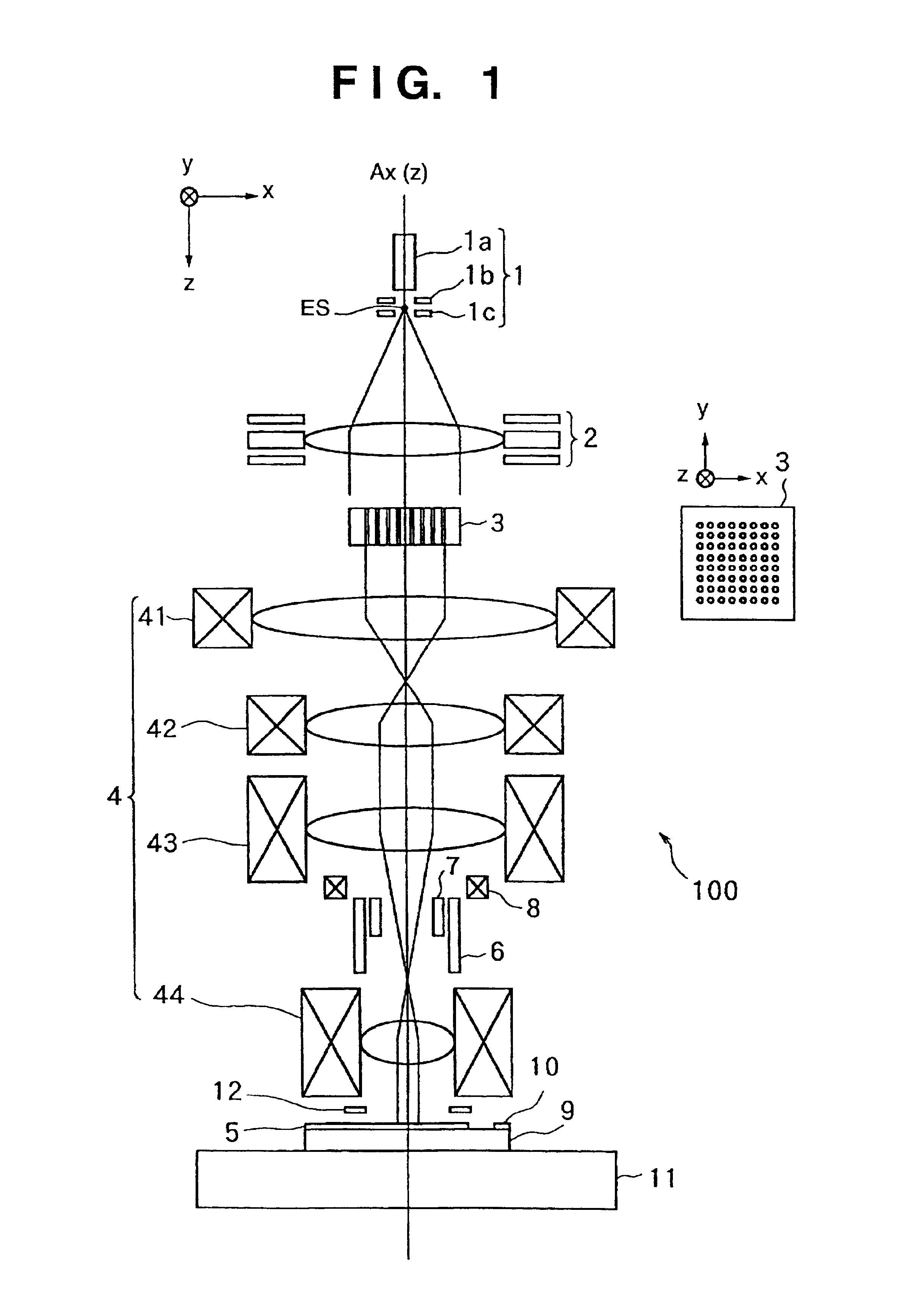
[0078]FIG. 1 is a schematic view showing an electron beam exposure apparatus according to a preferred embodiment of the present invention. Reference numeral 1 denotes an electron gun including a cathode 1a, grid 1b, and anode 1c. Electrons emitted by the cathode 1a form a crossover image as an electron source ES between the grid 1b and the anode 1c.

[0079]Electrons emitted by the electron source ES irradiate a correction electron optical system 3 via a condenser lens 2. The condenser lens 2 is comprised of, e.g., three aperture electrodes.

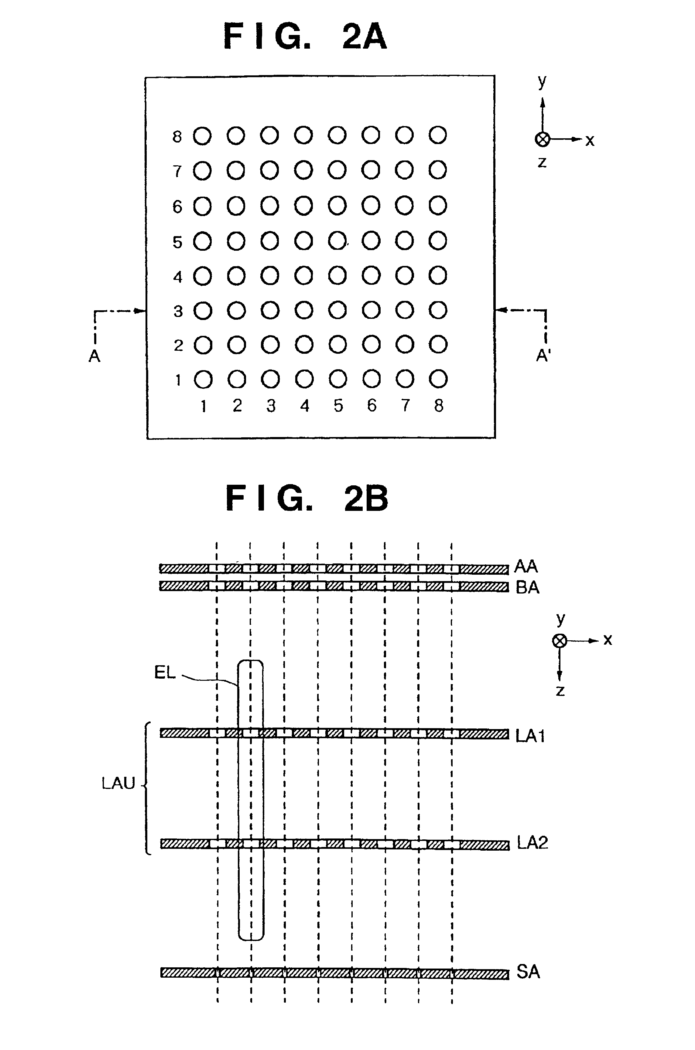
[0080]As shown in FIG. 2B, the correc...


PUM

PropertyMeasurementUnit
proximity effectaaaaaaaaaa
timeaaaaaaaaaa
forward scattering radiusaaaaaaaaaa

Abstract

A charged-particle beam exposure apparatus for exposing a member to be exposed to a charged particle beam with a pattern includes memories (902-905) for storing a plurality of control data for controlling reference dose data of the charged particle beam in accordance with the incident position of the charged particle beam on the member to be exposed, a selector (907) for selecting any one of the plurality of control data stored in the memories, and an exposure unit for controlling the reference dose data of the charged particle beam for each irradiation position on the basis of the control data selected by the selector, thereby exposing the member to be exposed with the pattern. The charged-particle beam exposure apparatus rapidly performs proper proximity effect correction to expose the member to be exposed with the pattern.

Description

FIELD OF THE INVENTION[0001]The present invention relates to a charged-particle beam exposure apparatus, an exposure method therefor, and a device manufacturing method using this method or the like and, more particularly, to a charged-particle beam exposure apparatus capable of rapidly, properly performing proximity effect correction in exposing a substrate to a charged particle beam with a pattern, an exposure method therefor, and a device manufacturing method using this method or the like.BACKGROUND OF THE INVENTION[0002]Recently, an electron beam drawing apparatus is used to draw a fine pattern on a sample such as a semiconductor wafer or mask substrate. This apparatus suffers the influence of a so-called proximity effect in which a pattern becomes thick or thin owing to backward scattering electrons.[0003]One of effective methods of correcting the proximity effect is a dosage correction method. As the method of determining the optimal dosage, there are adopted method (a) using a...

Claims


Application Information

Patent Timeline
Patent Type & Authority Patents(United States)
IPC IPC(8): H01J37/30H01J37/302H01J37/317H01J37/305G03F7/20H01L21/027
CPCB82Y10/00B82Y40/00H01J37/3174H01J37/3023H01J2237/30461
Inventor MURAKI, MASATOYUI, YOSHIKIYO
Owner CANON KK
Why Eureka
Try Eureka