
Method and apparatus for testing laminated cores of electrical machines

Inactive Publication Date: 2005-06-07
IRIS POWER
View PDF11 Cites 22 Cited by
  • Summary
  • Abstract
  • Description
  • Claims
  • Application Information

AI Technical Summary

Benefits of technology

[0015]The present invention overcomes the problem experienced by traditional ElCID testing apparatus when testing split hydrogenerator cores by operating at higher frequencies because smaller magnetic fields are generated by the excitation current near the stator teeth. By increasing the frequency of the excitation signal, the current required to produce a given electric field along the stator core is reduced. This means that the large Magnetic Potential Difference (MPDs) across any gaps and between the stator teeth are also reduced. Therefore, as the current through a fault is primarily determined by the level of the electric field and by the resistance of the fault, the fault currents in the stator core near the gaps are detected more reliably because the level of the unwanted magnetic field is reduced. Also the present invention reduces eddy current flow within the solid metal components associated with many electrical machines, for example, the rotor and its bearings, and so reduces the quadrature magnetic fields generated at and near the stator teeth. This is because the amplitude of the eddy currents are proportional to the amplitude of the excitation current and both the amplitude and phase-shift of the external magnetic fields produced by the eddy currents tend to be independent of frequency. This increases the resolution and accuracy of the results.
[0019]This is advantageous because one of the frequencies may typically be close to the optimum frequency. Another advantage is that it may be possible to analyse these signals to derive the effective resistance and inductance of the fault circuit at each frequency. These resistance and inductance values for the various frequencies may be then extrapolated back down to the rated operating frequency (usually 50 or 60 Hz), or even to DC, better to characterise the severity of the fault.

Problems solved by technology

The lamination insulation may, however, become damaged during assembly or maintenance of a stator, particularly during removal or replacement of the rotor.
The insulation may also degrade during operation, due to, for example, wear of the insulation.
If the insulation becomes damaged, then conducting circuits may be formed between laminations, through which fault currents are induced by the alternating magnetic flux.
These hot spots may damage the insulation on adjacent sections of the stator and can cause electrical breakdown and failure of the machine.
This type of test however requires a large amount of power and may not be able to detect deep seated core damage.
Additionally, these tests are labour intensive as the excitation windings are large.
This means that a small amount of power is required to conduct this test.
However, the test head is relatively large and heavy.
This means that the test head cannot traverse the stator core very easily.
Additionally, the test may not enable hot spots to be located precisely and so repairing the laminations may be difficult.
The ring flux induces fault currents in the stator core that flow through any potential hot spots, but these fault currents are too small to cause any detectable heating.
However there are several situations in which it is difficult to obtain reliable results using ElCID testing.
There can however be difficulties because the current through the excitation winding induces eddy currents in solid steel components such as the rotor and rotor bearings.
These eddy currents produce magnetic fields at the tips of the stator teeth that are not in phase with the excitation current and so can affect the ElCID test results such that faults are difficult to identify.
Since the phase and amplitude of these magnetic fields are not well defined it becomes very difficult using the standard ElCID test to determine whether there is a genuine fault in the core near the joins.
This is a serious drawback as damage is likely to occur at the joins in the core.

Method used


Image

  • Method and apparatus for testing laminated cores of electrical machines
  • Method and apparatus for testing laminated cores of electrical machines
  • Method and apparatus for testing laminated cores of electrical machines

Examples


Embodiment Construction

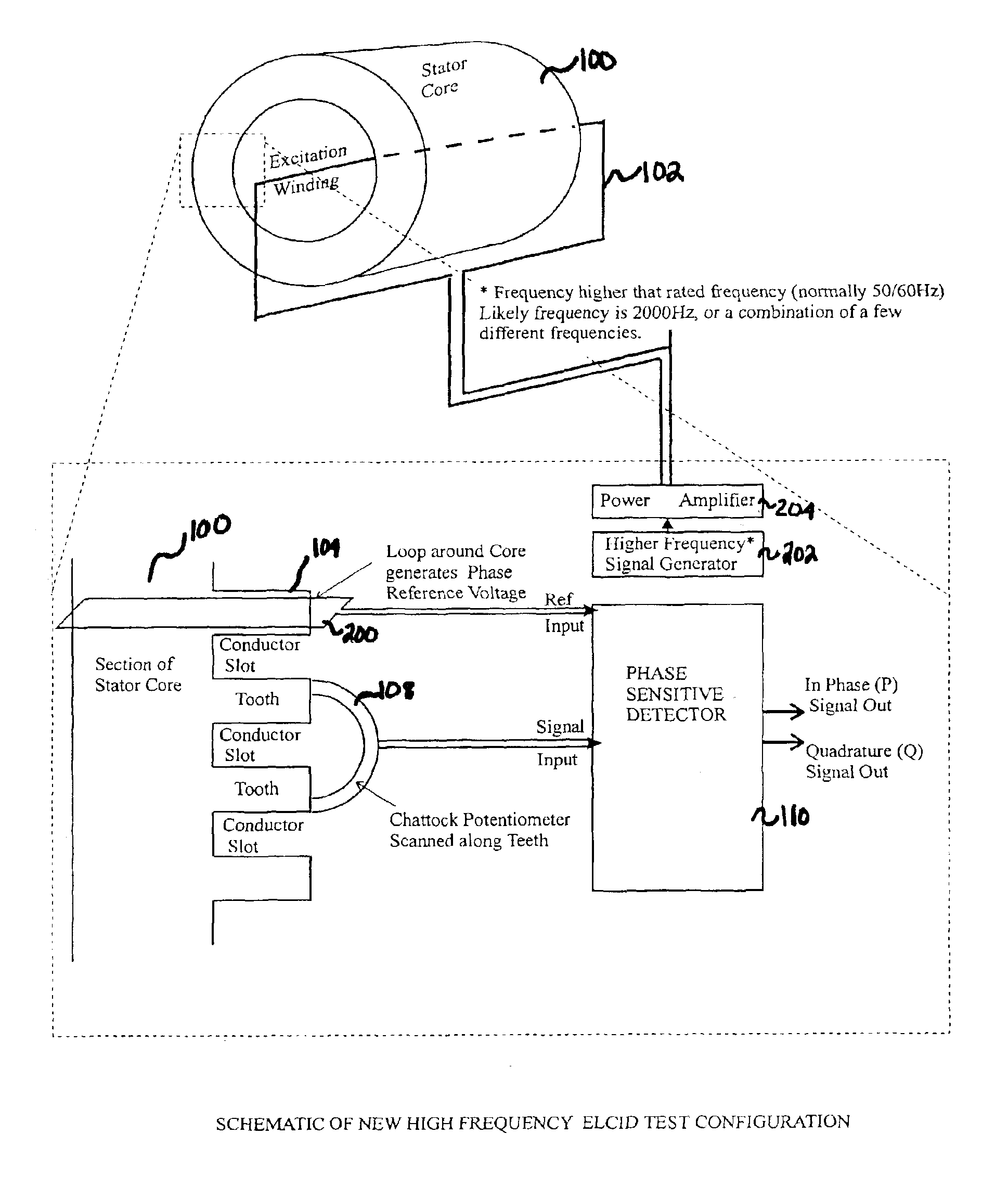
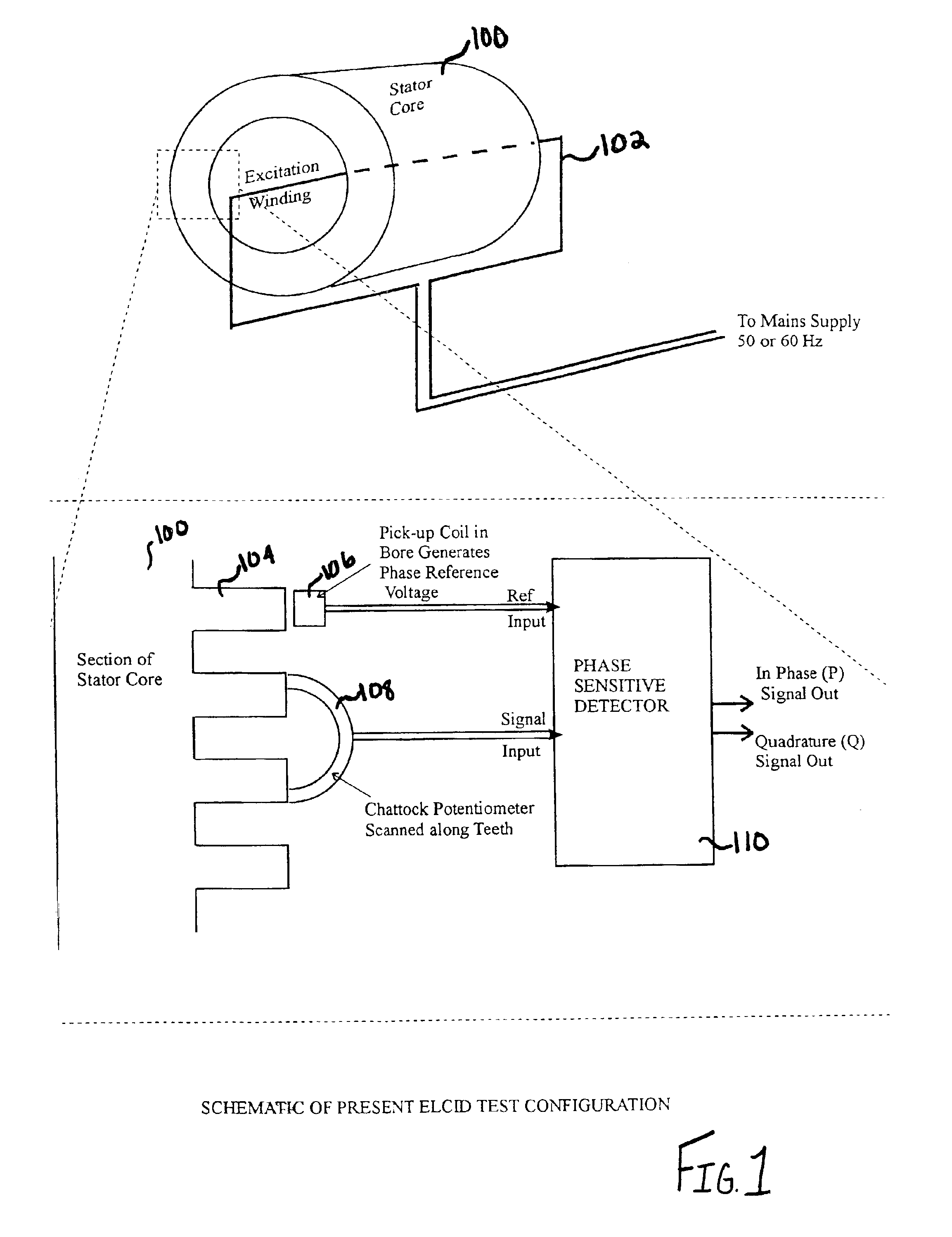
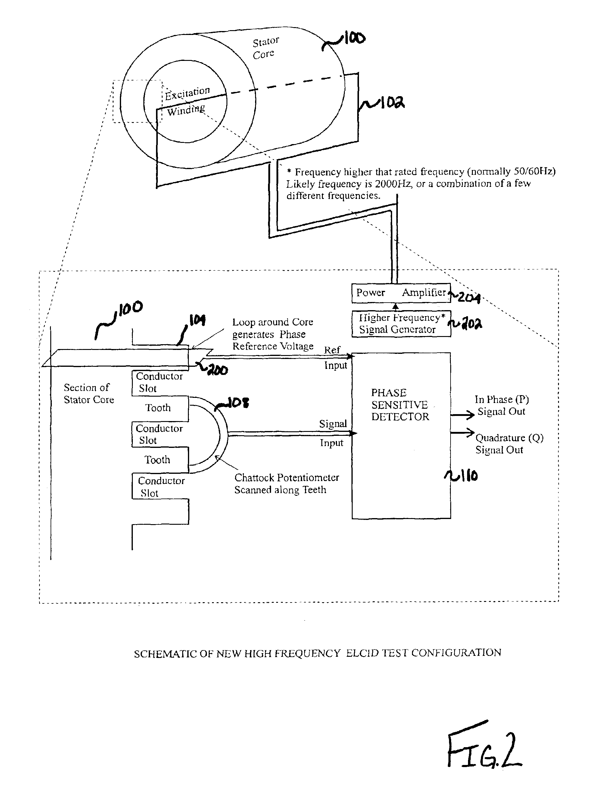
[0028]FIG. 1 shows a schematic of a typical known Electromagnetic Core Imperfection Detection (ElCID) test arrangement. This particular ElCID arrangement includes a laminated stator core 100. The stator core 100 is made up of layers of thin steel and insulation as is known. In large turbogenerators and some hydrogenerators, the stator core 100 is built up from layers of laminations which overlap all around the core. Many large hydrogenerator cores, however, are formed from two or more sectors, each built up from overlapping laminations, and the sectors are assembled on site. Small gaps therefore occur between where the sectors are joined. In use, a rotor (not shown) passes through the centre of the core 100. Typically during test, however, the rotor may be removed and an inserted excitation winding 102 passes through the centre of the core 100. However, as noted previously the stator 100 may be tested whilst the rotor is in place. It is also to be noted that key bars (not shown) whi...


PUM


Abstract

There is provided an apparatus and associated method for the testing of a laminated core (100) for an electrical machine. The apparatus supplies an excitation signal to the winding (102) of the electrical machine which is of a frequency higher than the rated operating frequency of the machine. There is also provided a phase sensitive detector (110) which receives, from the laminated core (100), a signal in response to the excitation signal. The phase sensitive detector (110) resolves the received signal into a number of components. These components are resolved relative to a reference signal. The size of the components determines the severity of any fault that exists within the laminated core (100.

Description

BACKGROUND TO THE INVENTION[0001]The present application claims priority of United Kingdom Patent Application Serial No. 0129020.4, filed 4 Dec. 2001, the contents which are hereby incorporated hereby in its entirety.[0002]The present invention relates to the testing of a laminated core of an electrical machine.[0003]The stator cores of generators and other electrical machines are built up of thin steel laminations which are each coated with a layer of electrical insulation. This insulation prevents the alternating magnetic flux, through the core, inducing unwanted eddy currents between the laminations.[0004]The lamination insulation may, however, become damaged during assembly or maintenance of a stator, particularly during removal or replacement of the rotor. The insulation may also degrade during operation, due to, for example, wear of the insulation.[0005]If the insulation becomes damaged, then conducting circuits may be formed between laminations, through which fault currents a...

Claims


Application Information

Patent Timeline
IPC IPC(8): G01R31/34
CPCG01R31/343
Inventor SUTTON, JOHN
Owner IRIS POWER
Features
  • Generate Ideas
  • Intellectual Property
  • Life Sciences
  • Materials
  • Tech Scout
  • Unparalleled Data Quality
  • Higher Quality Content
  • 60% Fewer Hallucinations
Learn More