Waterproofing and humidity control system

a technology for controlling system and humidity, which is applied in ventilation system, building repair, heating type, etc., can solve problems such as water seepage into buildings, plague the construction industry, and plague the below-ground foundation wall of buildings, so as to reduce the level of humidity and minimize the effect of water seepag

Inactive Publication Date: 2005-06-14
EVERDRY MARKETING & MANAGEMENT
View PDF27 Cites 41 Cited by
  • Summary
  • Abstract
  • Description
  • Claims
  • Application Information

AI Technical Summary

Benefits of technology

[0010]The present invention relates to a new and improved waterproofing and humidity control system. More specifically, the waterproofing and...

Problems solved by technology

The seepage of water into a building has been a problem which constantly plagues the construction industry.
This has been a problem for buildings which have basements as well as buildings built on a slab.
In particular, the seepage problem has plagued buildings having a below-ground foundation wall.
Even if the foundation wall is made from solid blocks or poured concrete, water may seep into the basement through cracks and by capillary action.
After a period of time, the drain tiles become non-functioning due to collapsing, blockage, separation, etc., and water accumulates at the bottom of the foundation wall, with a resultant build-up of hydrosta...

Method used


Image

  • Waterproofing and humidity control system
  • Waterproofing and humidity control system
  • Waterproofing and humidity control system

Examples


third embodiment

[0035]The fan of the fan and motor housing can be rated at about 177 cubic feet per minute (cfm) and have a noise level of about 48 decibels (db). In other words, a very quiet fan is used so as not to disturb occupants in the building. According to another embodiment, the fan can have a variable speed in order to have an output of anywhere from 100 to 300 cfm. The speed would be controlled by a speed selector knob (not illustrated). In yet a third embodiment, the fan speed can be varied anywhere from 0 to 250 cfm. The fan speed may need to be varied depending upon the amount of square feet in the basement. It is anticipated that at around 150 to 200 cfm, the system of the present invention can handle approximately 1300 square feet of basement floor surface, that is a basement of about 35 feet by 35 feet. The cfm rating is to ensure an enhanced airflow from the basement. The fan is typically of a conventional cage and barrel design.

[0036]Referring now to FIG. 2, the motor and fan hou...

second embodiment

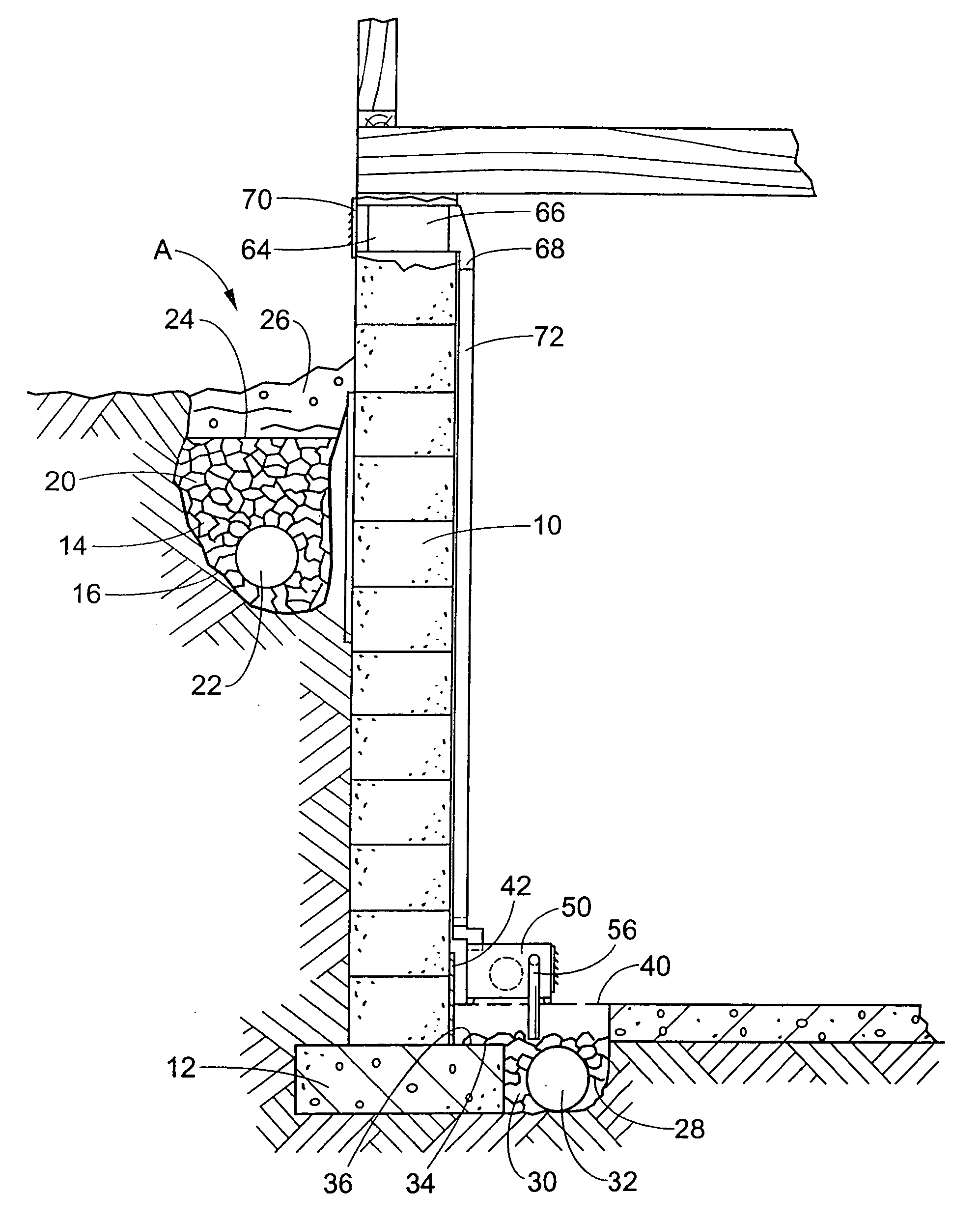
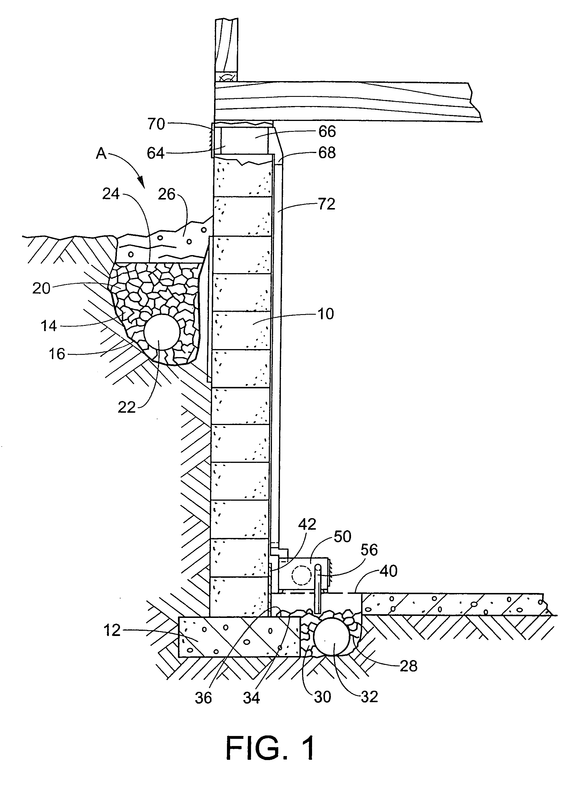
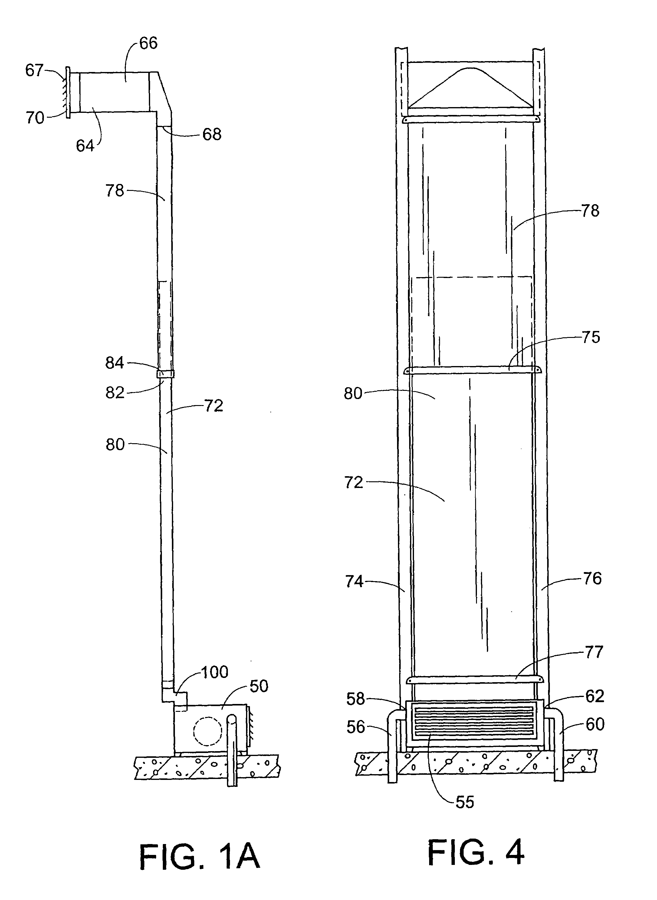
[0041]The duct is typically no more than 13.5 inches wide. The thickness of the duct typically ranges from 2½–3 inches maximum. In FIGS. 1A and 4, the duct comprises a first portion 78 and second portion 80. The first portion 78 has a larger outer dimension than the outer dimension of the second portion. The second portion is thus slidably received in an opening 82 of the first portion adjacent a flange 84. The second portion 80 is thus adjustable in relation to the first portion to accommodate different basement heights. The height of the duct can range from 60 inches to about 102 inches by simply sliding the second portion with respect to the first portion.

[0042]Referring now to FIGS. 2 and 3, an adapter conduit 100 can be provided between the motor and fan housing and the third conduit or duct 72. The adapter conduit is used in a situation where the humidity control system is installed in a home with a finished basement wall. The adapter conduit has a first portion 102 and a seco...


PUM


Abstract

A waterproofing and humidity control system is provided for a building which includes drain members located in trenches provided in ground beneath and adjacent the basement of the building. A suction and fan and motor assembly is located within a housing positioned within the building. Conduits communicate with the drain members and the motor and fan housing. An exhaust vent is located in the wall of the building spaced from the motor housing and has an air inlet and outlet. A separate conduit or duct communicates with and connects the inlet of the vent with an outlet of the motor and fan housing. The duct may extend between joints in the wall of the building. An adapter conduit is used with the system and is positioned between the motor and fan housing and the duct. The adapter conduit has portions which are offset from each other to allow the fan housing to be positioned in front of a finished basement wall.

Description

BACKGROUND OF THE INVENTION[0001]The present invention relates to a system for preventing water from seeping into a building and for controlling humidity in a basement of a building, and in particular relates to a waterproofing and humidity control system for a house.[0002]The seepage of water into a building has been a problem which constantly plagues the construction industry. This has been a problem for buildings which have basements as well as buildings built on a slab. In particular, the seepage problem has plagued buildings having a below-ground foundation wall.[0003]It is known that the foundation wall of a building is most often made from hollow concrete blocks or poured concrete. With blocks, water is able to pass from the exterior surrounding ground of the building through cracks, holes, natural pores, etc. in the block into hollow cavities of the block and thence to the basement floor. Even if the foundation wall is made from solid blocks or poured concrete, water may see...

Claims


Application Information

Patent Timeline
IPC IPC(8): E02D31/00E02D31/02
CPCE02D31/02Y10S52/90Y10S454/909
Inventor MOORE, CARL P.DICELLO, NICHOLAS D.
Owner EVERDRY MARKETING & MANAGEMENT
Why Eureka
Try Eureka