Cylindrical neutron generator

a neutron generator and cylindrical technology, applied in nuclear reactors, nuclear engineering, greenhouse gas reduction, etc., can solve the problems of limited neutron production, limited neutron yield, and limited neutron yield, so as to increase the neutron flux, high current density, and high atomic species

Inactive Publication Date: 2005-06-14
RGT UNIV OF CALIFORNIA
View PDF11 Cites 41 Cited by
  • Summary
  • Abstract
  • Description
  • Claims
  • Application Information

AI Technical Summary

Benefits of technology

[0012]A more complex embodiment of the neutron generator, which combines the two basic embodiments, has a nested configuration that is formed by nesting concentric targets and plasma regions. The nested configuration places a coaxial target both inside and outside the plasma generating region, and nests several targets and plasma generating regions to increase the neutron flux.
[0013]This invention enables the generator to operate with high current density, high atomic species and practically unlimited beam size in the axial or longitudinal direction. The structure is compact and rugged, e.g. the RF antenna can form part of the plasma electrode and chamber wall. Thus the source's lifetime should be greatly increased because no weak components exist. The geometry is ideal for borehole applications. The source is ideal for many neutronic applications. Because of the increased target area, the much safer D-D reaction can be used, eliminating any tritium from the source.

Problems solved by technology

Neutron yield is limited by the ion source performance and beam size.
The production of neutrons is limited by the beam current and power deposition on the target.
In the conventional neutron tube, the extraction aperture and the target are limited to small areas, and so is the neutron output flux.
The deuterium-on-deuterium (D-D) reaction, with a cross section for production a hundred times lower, has not been able to provide the necessary neutron flux.
This will greatly increase the lifetime of the neutron generator, which is unsatisfactory at present.
As for the others, RFQ-based sources have never become a major commercial presence due to cost and complexity, and the safety concerns and lack of time structure that are inherent to isotopic sources limit their applications.
Detecting such materials hidden in baggage or cargo is challenging under real-world conditions.
The first-generation TNA screeners were too large, complex, and expensive; FAA-approved screening devices presently on the market use x-rays to look at shapes and densities, rather than using neutronics to detect actual composition.

Method used


Image

  • Cylindrical neutron generator
  • Cylindrical neutron generator
  • Cylindrical neutron generator

Examples


Embodiment Construction

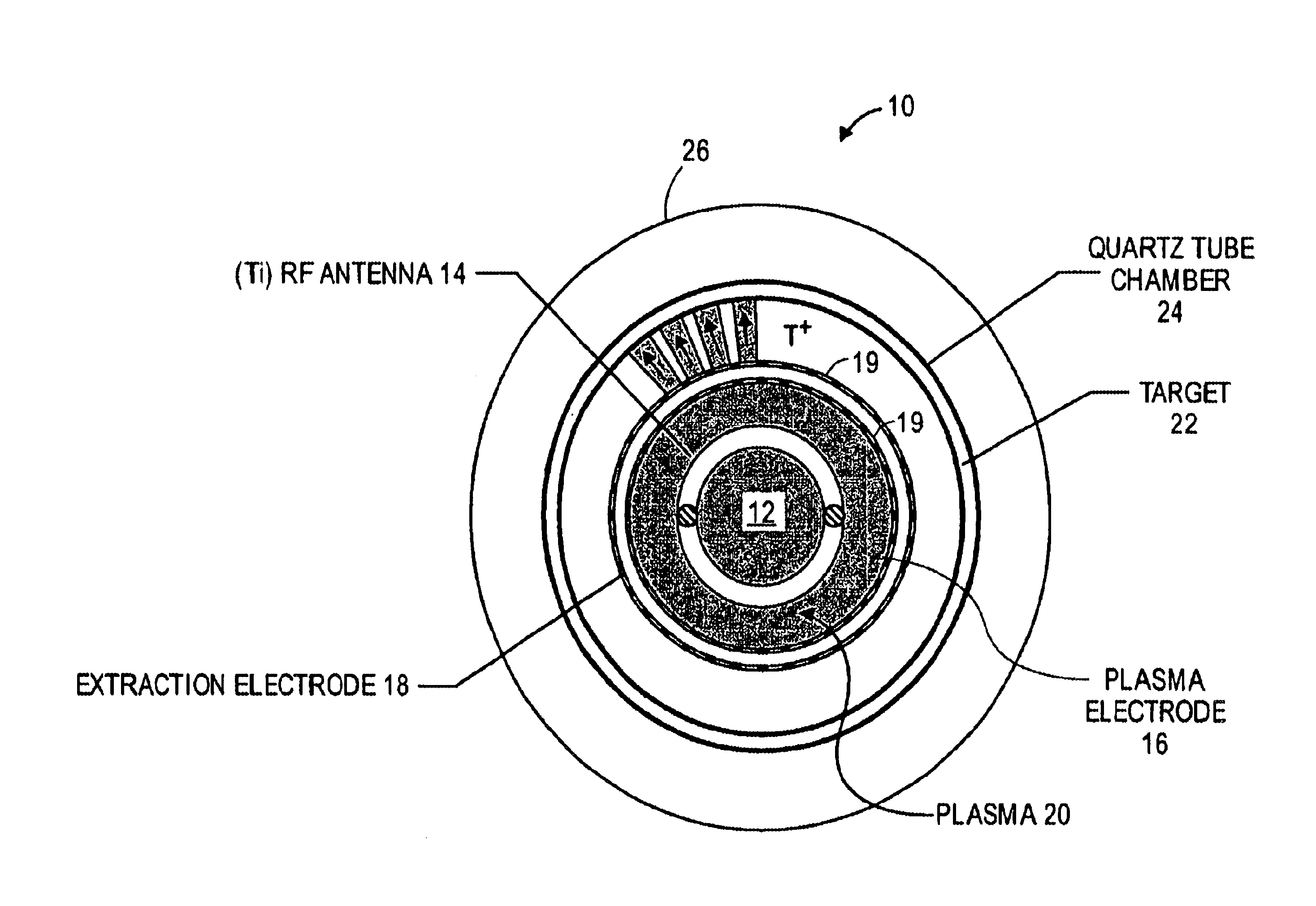
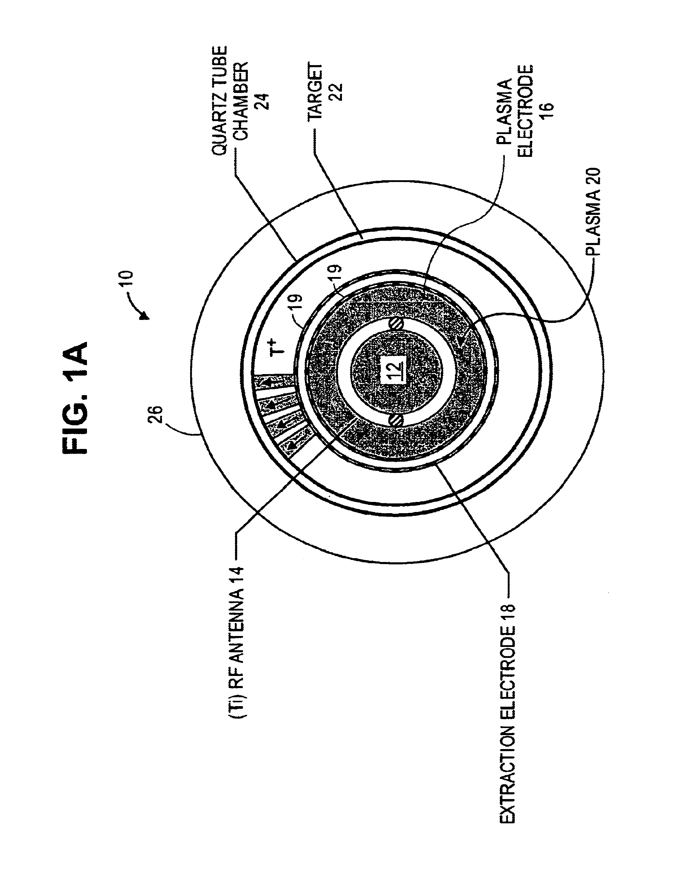
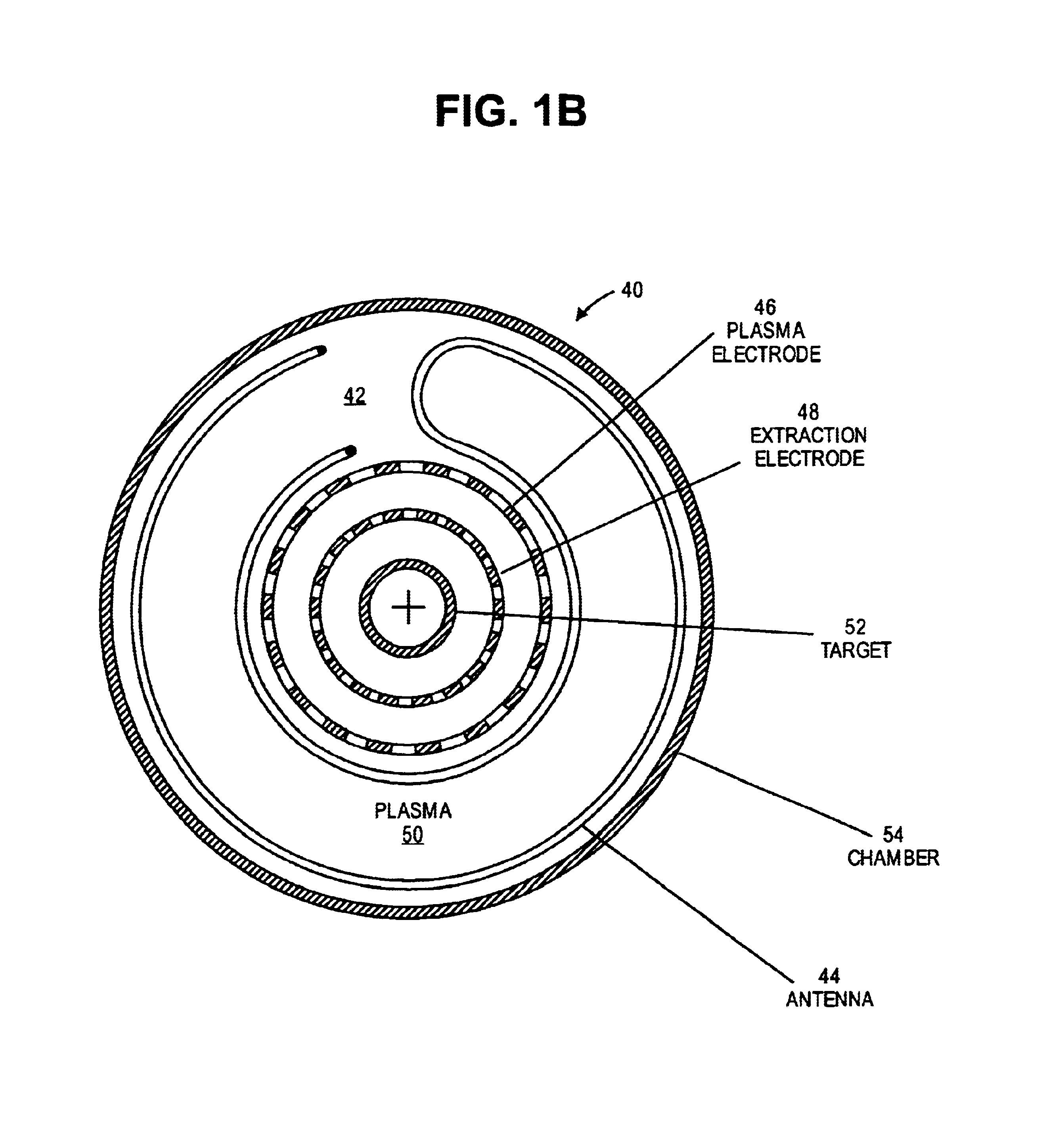
[0023]FIGS. 1A, 2A, 3A show the neutron source geometry of a first embodiment 10 of the invention, which has a cylindrical neutron generating target outside a cylindrical plasma ion source. Neutron generator 10 has a cylindrical plasma ion source 12 at its center. The principles of plasma ion sources are well known in the art. Conventional multicusp ion sources are illustrated by U.S. Pat. Nos. 4,793,961; 4,447,732; 5,198,677; 6,094,012, which are herein incorporated by reference.

[0024]Ion source 12 includes an RF antenna (induction coil) 14 for producing an ion plasma 20 from a gas which is introduced into ion source 12. Antenna 14 is typically made of titanium tubing, which may be water cooled. For neutron generation the plasma is preferably a deuterium ion plasma but may also be a deuterium and tritium plasma. A deuterium plasma with current density of about 100 mA / cm2 can be produced. Ion source 12 also includes a pair of spaced electrodes, plasma electrode 16 and extraction ele...


PUM


Abstract

A cylindrical neutron generator is formed with a coaxial RF-driven plasma ion source and target. A deuterium (or deuterium and tritium) plasma is produced by RF excitation in a cylindrical plasma ion generator using an RF antenna. A cylindrical neutron generating target is coaxial with the ion generator, separated by plasma and extraction electrodes which contain many slots. The plasma generator emanates ions radially over 360° and the cylindrical target is thus irradiated by ions over its entire circumference. The plasma generator and target may be as long as desired. The plasma generator may be in the center and the neutron target on the outside, or the plasma generator may be on the outside and the target on the inside. In a nested configuration, several concentric targets and plasma generating regions are nested to increase the neutron flux.

Description

RELATED APPLICATIONS[0001]This application claims priority of Provisional Applications Ser. Nos. 60 / 276,669 filed Mar. 16, 2001 and 60 / 316,792 filed Aug. 31, 2001.GOVERNMENT RIGHTS[0002]The U.S. Government has rights in this invention pursuant to Contract No. DE-AC03-76SF00098 between the U.S. Department of Energy and the University of California.BACKGROUND OF THE INVENTION[0003]The invention relates to neutron tubes or sources, and more particularly to neutron tubes or sources based on plasma ion generators, including compact neutron tubes or sources which generate a relatively high neutron flux using the D-D reaction.[0004]Conventional neutron tubes employ a Penning ion source and a single gap extractor. The target is a deuterium or tritium chemical embedded in a molybdenum or tungsten substrate. Neutron yield is limited by the ion source performance and beam size. The production of neutrons is limited by the beam current and power deposition on the target. In the conventional neu...

Claims


Application Information

Patent Timeline
Patent Type & Authority Patents(United States)
IPC IPC(8): G21B3/00
CPCG21B3/00Y02E30/18Y02E30/10
Inventor LEUNG, KA-NGO
Owner RGT UNIV OF CALIFORNIA
Why Eureka
Try Eureka