Neutral particle beam processing apparatus

a technology of neutron beam and processing apparatus, which is applied in mechanical apparatus, machines/engines, instruments, etc., can solve the problems that the radiation produced by the plasma is not substantially applied to the workpiece, and achieve the effect of high neutralization efficiency, compact structure and low cos

Inactive Publication Date: 2005-06-21
TOHOKU TECHNO ARCH CO LTD
View PDF6 Cites 8 Cited by
  • Summary
  • Abstract
  • Description
  • Claims
  • Application Information

AI Technical Summary

Benefits of technology

[0007]The present invention has been made in view of the above drawbacks. It is therefore an object of the present invention to provide a neutral particle beam processing apparatus which can apply an energetic beam having a large beam diameter to a workpiece with an inexpensive and compact structure, and can neutralize ions with a high neutralization efficiency to process the workpiece without a charge build-up or damage.
[0009]With the above arrangement, since the workpiece can be processed by a neutral particle beam having no electric charges but having a large translational energy, various processes including an etching process and a deposition process can be performed on the workpiece with high accuracy in such a state that an amount of charge build-up is reduced. Particularly, when the orifice electrode is used for neutralizing the negative ions, a high neutralization efficiency can be obtained, and hence a beam diameter of an energetic beam can be increased inexpensively without increasing the size of the apparatus. Further, since the generated plasma is isolated from the workpiece by the orifice electrode, a radiation produced by the plasma is not substantially applied to the workpiece. Therefore, it is possible to reduce adverse effects on the workpiece due to the radiation such as an ultraviolet ray which would otherwise damage the workpiece.
[0011]With the above arrangement, the orifice electrode serves not only to neutralize the negative ions, but also to generate the plasma. Therefore, a high neutralization efficiency can be obtained by the orifice electrode, and simultaneously it is not necessary to provide a separate plasma generator for generating a plasma. Thus, the neutral particle beam processing apparatus can be made compact in structure, and a beam diameter of an energetic beam can be increased inexpensively.
[0012]Preferably, the orifice electrode has a thickness which is at least twice the diameter of the orifices defined therein. When the orifice electrode has a thickness which is at least twice the diameter of the orifices, it is possible to increase the probability that the negative ions are neutralized in the orifices, and to remarkably reduce the intensity of a radiation to be applied to the workpiece from the plasma.

Problems solved by technology

Further, since the generated plasma is isolated from the workpiece by the orifice electrode, a radiation produced by the plasma is not substantially applied to the workpiece.

Method used


Image

  • Neutral particle beam processing apparatus
  • Neutral particle beam processing apparatus
  • Neutral particle beam processing apparatus

Examples


first embodiment

[0022]A neutral particle beam processing apparatus according to the present invention will be described in detail below with reference to FIGS. 1 through 3.

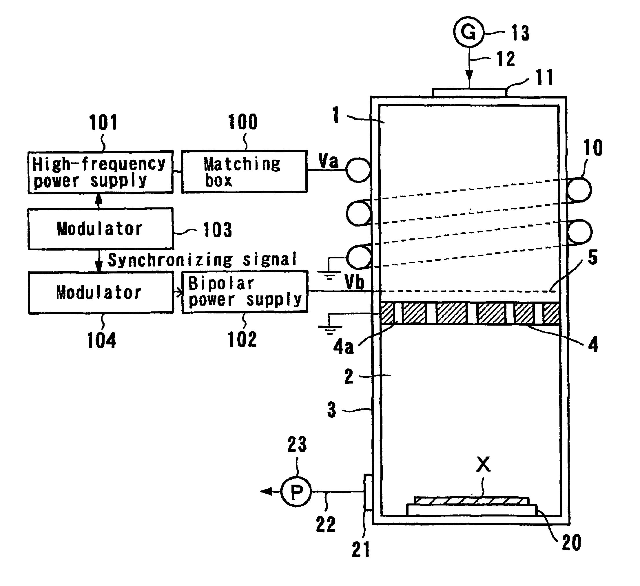
[0023]FIG. 1 is a schematic view showing a whole arrangement of a neutral particle beam processing apparatus according to a first embodiment of the present invention, with electric components in block form. As shown in FIG. 1, the neutral particle beam processing apparatus comprises a cylindrical vacuum chamber 3 constituted by a beam generating chamber 1 for generating a neutral particle beam and a process chamber 2 for processing a workpiece X such as a semiconductor substrate, a glass workpiece, an organic workpiece, a ceramic workpiece, or the like. The beam generating chamber 1 of the vacuum chamber 3 has walls made of quartz glass or ceramics, and the process chamber 2 of the vacuum chamber 3 has walls made of metal.

[0024]The beam generating chamber 1 has a coil 10 disposed therearound for inductively coupled plasma (ICP). ...

second embodiment

[0046]Operation of the neutral particle beam processing apparatus will be described below. FIG. 6 is a timing chart showing operating states of the neutral particle beam processing apparatus shown in FIG. 5. In FIG. 6, Vc represents the potential of the AC power supply 105, Te the electron temperature in the beam generating chamber 1, ne the electron density in the beam generating chamber 1, ni− the negative ion density in the beam generating chamber 1, Vd the potential of the DC power supply 106, and Ve the potential of the orifice electrode 4. The timing chart is schematically shown in FIG. 6, and the shown frequencies are different from the actual frequencies, for example.

[0047]The vacuum pump 23 is driven to evacuate the vacuum chamber 30, and then a gas is introduced from the gas supply source 13 into the beam generating chamber 1. As shown in FIG. 6, a high-frequency voltage having a frequency of about 13.56 MHz is applied to the orifice electrode 4 for 10 microseconds by the...


PUM

PropertyMeasurementUnit
frequencyaaaaaaaaaa
diameteraaaaaaaaaa
frequencyaaaaaaaaaa

Abstract

A neutral particle beam processing apparatus comprises a workpiece holder (20) for holding a workpiece (X), a plasma generator for generating a plasma in a vacuum chamber (3) by applying a high-frequency electric field, an orifice electrode (4) disposed between the workpiece holder (20) and the plasma generator, and a grid electrode (5) disposed upstream of the orifice electrode (4) in the vacuum chamber (3). The orifice electrode (4) has orifices (4a) defined therein. The neutral particle beam processing apparatus further comprises a voltage applying unit for applying a voltage between the orifice electrode (4) which serves as an anode and the grid electrode (5) which serves as a cathode, while the high-frequency electric field applied by the plasma generator is being interrupted, to accelerate negative ions in the plasma generated by the plasma generator and pass the accelerated negative ions through the orifices (4a) in the orifice electrode (4).

Description

TECHNICAL FIELD[0001]The present invention relates to a neutral particle beam processing apparatus, and more particularly to a neutral particle beam processing apparatus for generating a highly directional and highly dense neutral particle beam from a high-density plasma and processing a workpiece with the generated neutral particle beam.BACKGROUND ART[0002]In recent years, semiconductor integrated circuits, information storage media such as hard disks, micromachines, and the like have been processed in highly fine patterns. In the fields of processing such workpieces, attention has been attracted to the use of an energetic beam such as a high-density ion beam which is highly linear, i.e., highly directional, and has a relatively large beam diameter. For example, the energetic beam is applied to a workpiece for depositing a film thereon or etching the workpiece.[0003]As beam sources of such energetic beams, there have been used beam generators which generate various kinds of beams i...

Claims


Application Information

Patent Timeline
Patent Type & Authority Patents(United States)
IPC IPC(8): H05H3/02H05H3/00H05H1/46C23C14/32H01J37/32H01L21/302H01L21/3065H01L21/31
CPCH05H3/02
Inventor SAMUKAWA, SEIJIICHIKI, KATSUNORIYAMAUCHI, KAZUOHIYAMA, HIROKUNI
Owner TOHOKU TECHNO ARCH CO LTD
Why Eureka
Try Eureka