Method and device for fusing toner onto a substrate

a technology of toner and substrate, which is applied in the direction of electrographic process equipment, instruments, optics, etc., can solve the problems of limited chance of positively influencing the gloss of the print image, narrow confinement of temperature change, transfer and subsequent printing could be damaged, etc., to achieve high electric field strength, increase the efficiency of the microwave system, and increase the effect of electric field strength

Inactive Publication Date: 2005-06-21
EASTMAN KODAK CO
View PDF6 Cites 12 Cited by
  • Summary
  • Abstract
  • Description
  • Claims
  • Application Information

AI Technical Summary

Benefits of technology

[0021]The height of a resonator in the substrate transfer direction is optimized to achieve a high electric field strength, without discharges into the applicator. Good results are thus achieved with heights such as 54 mm, 34 mm, 24 mm, and 20 mm. The smaller values are preferred for higher electric field strength. High electric field strength increases the efficiency of the microwave system for substrates with lower losses, as with paper, for example.
[0022]The frequency modulation of a resonant applicator is size-dependent in the machine direction (lengthwise). After a longer operating period, the heating o

Problems solved by technology

For example, by just fusing with a fusing roller, there is a limited chance of positively influencing the gloss of the print image.
This can occur to a certain extent due to a change in the fusing roller temperature; however, such a temperature change is narrowly confined due to the narrow boundaries of the so-called “cold offset”

Method used


Image

  • Method and device for fusing toner onto a substrate
  • Method and device for fusing toner onto a substrate

Examples


example 1 (table 1)

[0037]

Toner / FusingPaperPaperRollerSurfacePaperFusingTem-Tem-Tem-SpeedTimeperatureperatureperatureComment 30 cm / s60 ms27° C.160° C.110° C.No MicrowaveHeating 45 cm / s40 ms44° C.160° C.110° C.2 × 1500 kW 60 cm / s30 ms54° C.160° C.110° C.2 × 2000 kW 90 cm / s20 ms65° C.160° C.110° C.4 × 2000 kW120 cm / s15 ms72° C.160° C.110° C.4 × 3200 kW

example 2 (table 2)

[0038]

Toner / FusingPaperPaperRollerSurfacePaperFusingTem-Tem-Tem-SpeedTimeperatureperatureperatureComment 30 cm / s60 ms27° C.160° C.112° C.No MicrowaveHeating 45 cm / s40 ms40° C.160° C.112° C.2 × 1500 kW 60 cm / s30 ms48° C.160° C.112° C.2 × 2000 kW 90 cm / s20 ms59° C.160° C.110° C.4 × 2000 kW120 cm / s15 ms67° C.160° C.110° C.4 × 3200 kW

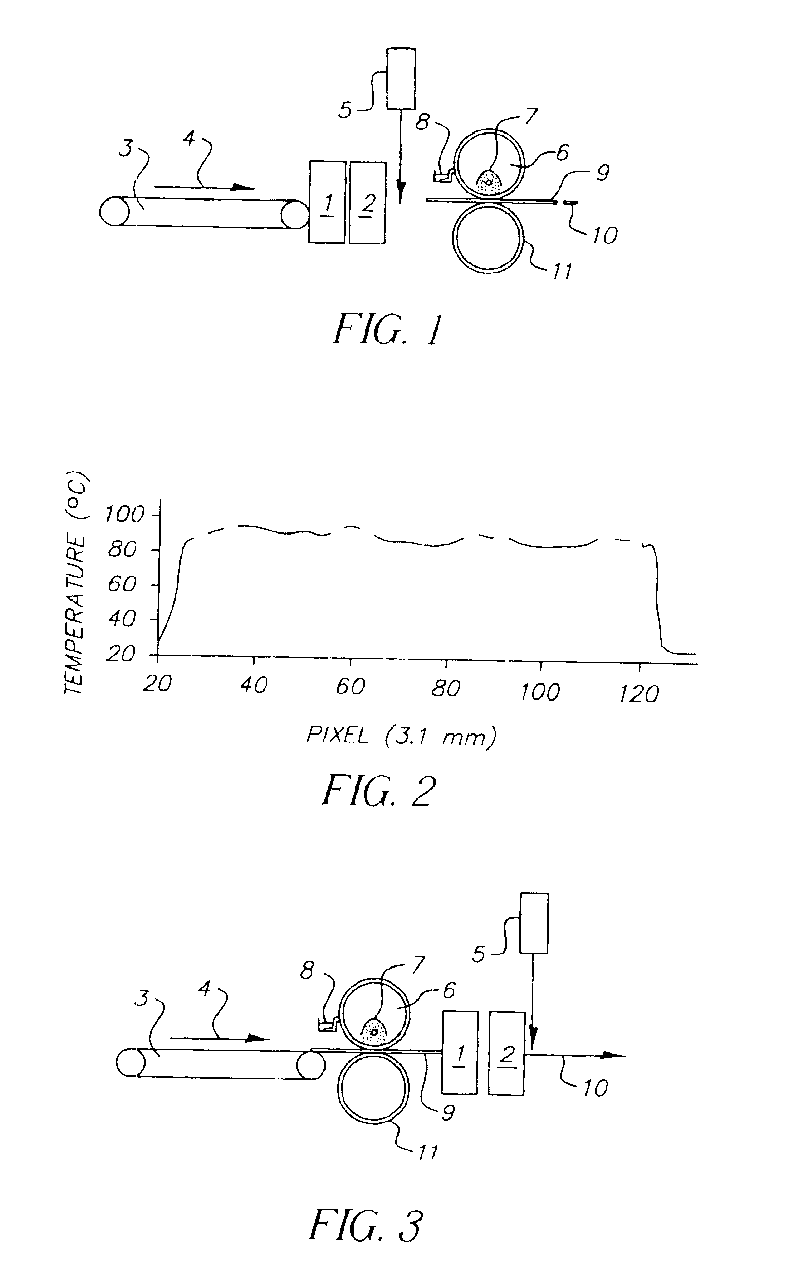
[0039]The tables show the paper speed, the fusing time per nip of the fusing roller of 18 mm, and the paper temperature at the exit of the microwave heating device, which is required in order to reach a paper-to-toner surface or interface temperature of approximately 110° C., which is necessary to fuse conventional toner with a fusing roller surface temperature of 160° C. The data specified are experimental and calculated from models.

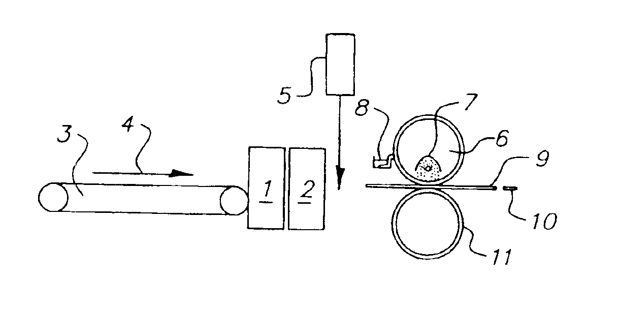
[0040]FIG. 3 shows a second embodiment of a combination of a microwave heating and a fusing roller according to the invention. The same components are designated with the same reference numbers as in FIG. 1. The line pyrometer ...


PUM


Abstract

A fusing device complemented by a microwave application.

Description

FIELD OF THE INVENTION[0001]The invention relates to a method and device for fusing toner onto a substrate, wherein a fusing device (fuser), preferably including one heatable fusing rollers in contact with the toner, is used to heat the toner to a temperature that is higher or equal to its glass transition (vitrification) temperature.BACKGROUND OF THE INVENTION[0002]Electrostatic and electrophotographic printing involves developing a latent electrostatic image with charged toner particles loaded onto an imaging drum and transferring them onto a substrate or a print substrate, particularly in the form of sheets or in the form of a continuous conveyor belt. As an example, in four-color printing, four latent images in the four-color separations (cyan, magenta, yellow, and black) are transferred to the substrate successively and in register on top of one other. In particular, the finished single color or multicolored latent image is then fused onto the substrate by a fusing device. This...

Claims


Application Information

Patent Timeline
IPC IPC(8): G03G15/20
CPCG03G15/2064G03G15/2007
Inventor BEHNKE, KNUTDRAGER, UDOKRAUSE, HANS-OTTOMORGENWECK, FRANK-MICHAELROHDE, DOMINGOSCHULZE-HAGENEST, DETLEF
Owner EASTMAN KODAK CO
Why Eureka
Try Eureka