Unlock instant, AI-driven research and patent intelligence for your innovation.
Method for the treating in exhaust gas and exhaust gas treating system
Inactive Publication Date: 2005-07-05
MITSUBISHI HEAVY IND LTD
View PDF6 Cites 16 Cited by
Summary
Abstract
Description
Claims
Application Information
AI Technical Summary
This helps you quickly interpret patents by identifying the three key elements:
Problems solved by technology
Method used
Benefits of technology
Benefits of technology
[0009]In view of the above-described problems, the present inventors made intensive investigations for the purpose of developing a mercury removal method employed in an exhaust gas treatment system to remove mercury (in particular, metallic mercury vapor) contained in a large-volume gas such as exhaust gas from an electric powerplant. This method properly controls or regulates the amount of chlorinating agent added to remove mercury and thereby makes it possible to achieve efficient operation of the system and maintain the performance thereof without exerting any adverse influence on the downstream units.
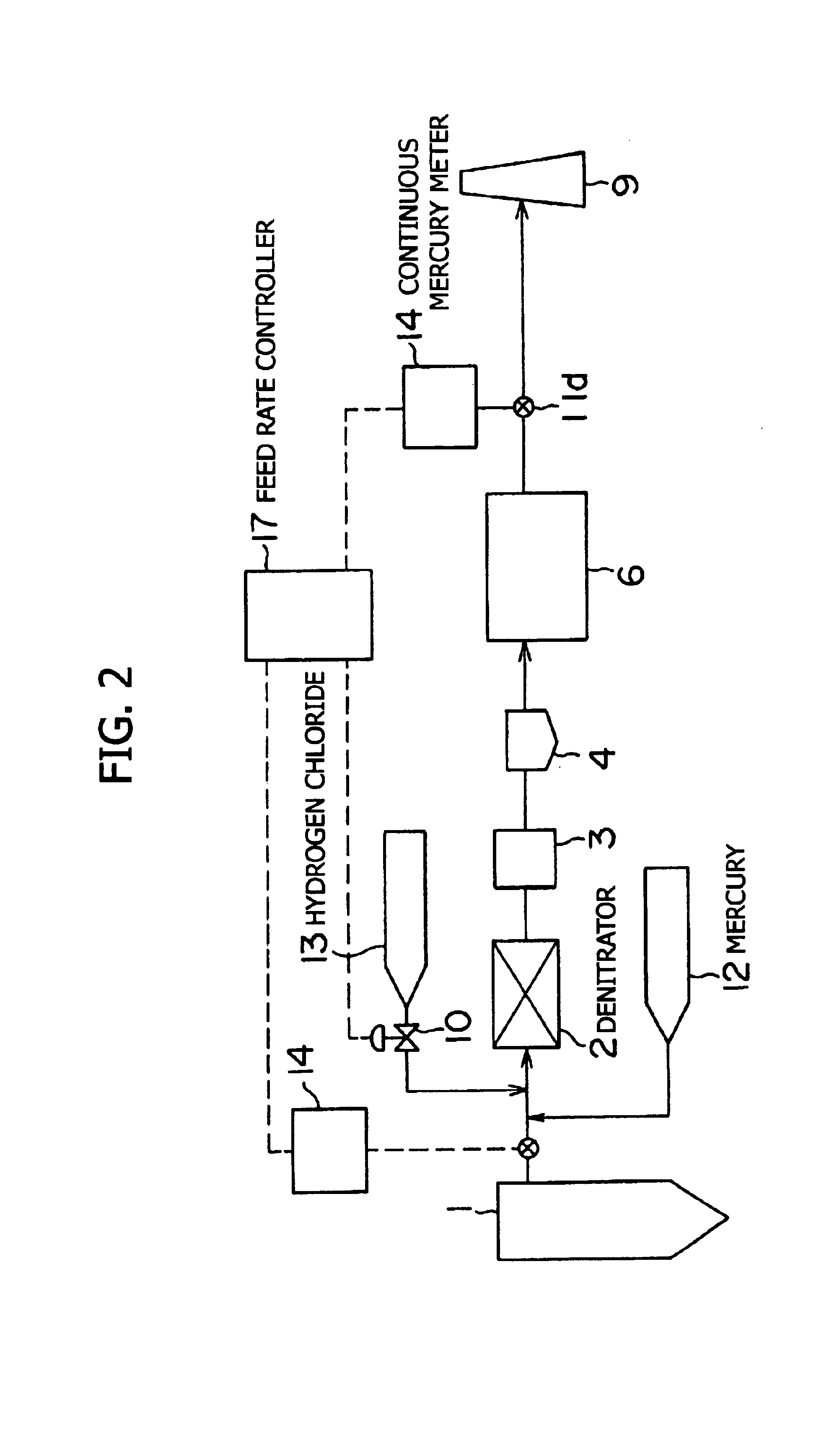
[0013]Furthermore, the present invention provides a method for the treatment of mercury present in exhaust gas wherein, after a chlorinating agent is added to exhaust gas containing nitrogen oxides, sulfur oxides and mercury, the exhaust gas is subjected to a reductive denitration treatment in the presence of a solid catalyst and then to wet desulfurization using an alkaline absorbing fluid, the method being characterized by measuring the mercury concentration in the exhaust gas before and after the wet desulfurization; and controlling the feed rate of the added chlorinating agent prior to the reductive denitration treatment, according to the deviation of each of the measured mercury concentrations from a reference mercury concentration. According to this method, the accuracy of a predicted value of the mercury concentration can be improved by detecting the boiler load or the operating load signal of the electrostatic precipitator and the desulfurizer.
[0015]Thus, the present invention provides a mercury removal method employed in an exhaust gas treatment system to remove mercury (in particular, metallic mercury vapor) contained in a large-volume gas such as exhaust gas from an electric powerplant, which controls or regulates properly the amount of chlorinating agent added for the removal of mercury and thereby makes it possible to achieve efficient operation of the system and maintain the performance thereof without exerting any adverse influence on the downstream units.
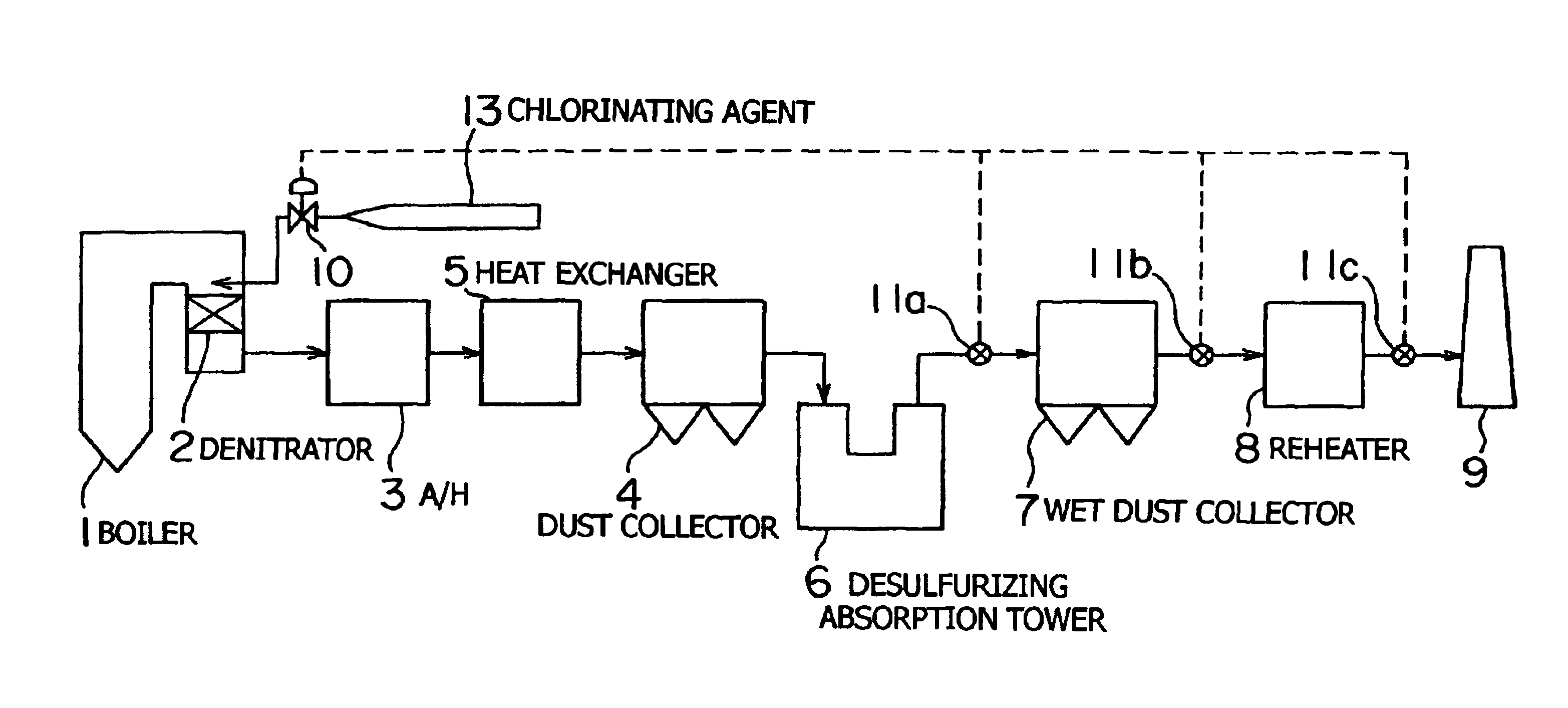
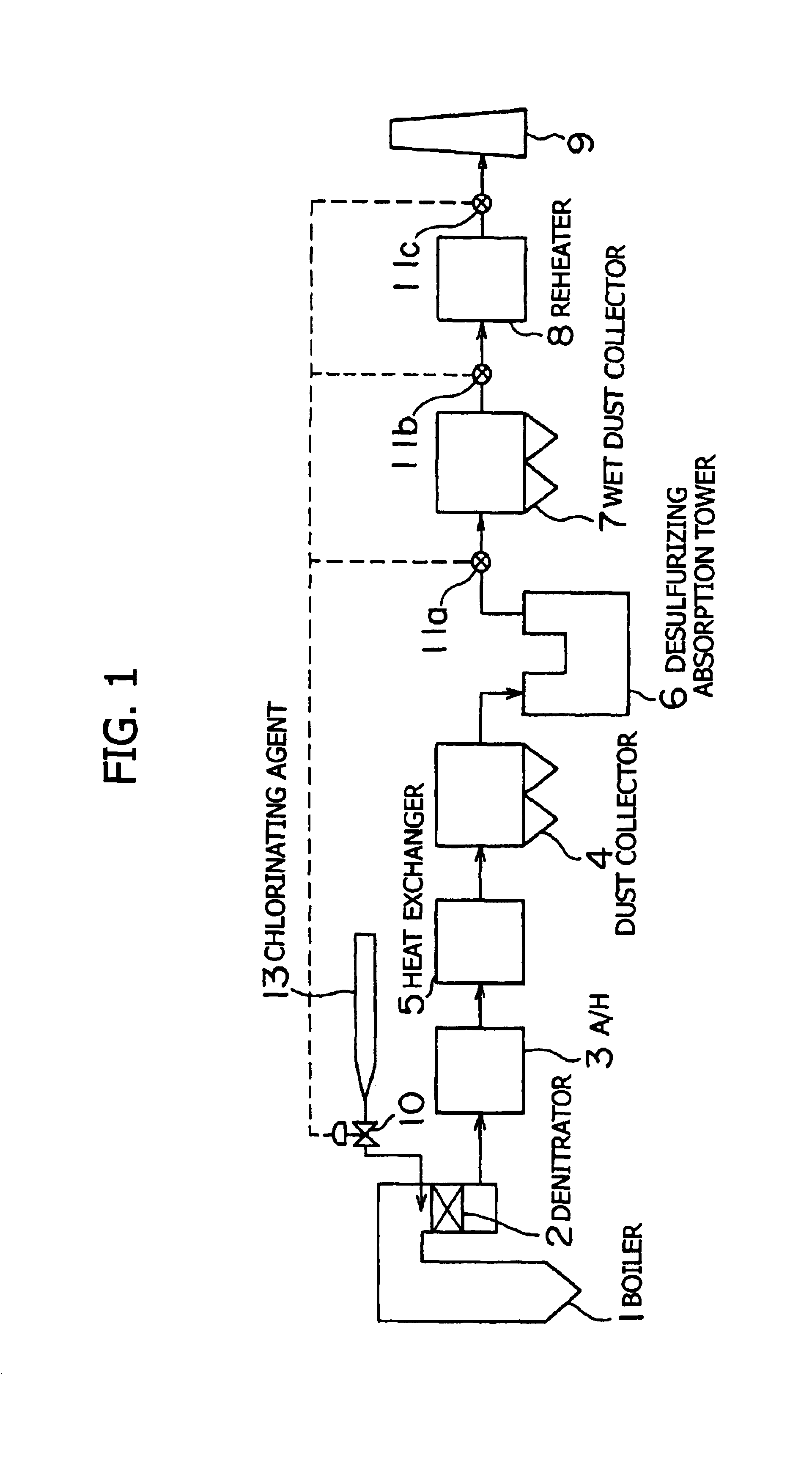
[0016]Specifically, with respect to the units installed on the downstream side of the denitrator, such as the air heater, dust collector, gas-gas heater (heat exchanger) and desulfurizing absorption tower, the problem of corrosion or damage due to the addition of an excess of the chlorinating agent can be prevented effectively. Moreover, since an increase in chlorine concentration within the desulfurizing absorption tower is suppressed, a reduction in oxidation capability or desulfurization capability during desulfurization and an increase in the foamability of the absorbing fluid can also be prevented. Thus, the overall performance of the system, including the desulfurization capability, can be maintained or improved.
[0017]Furthermore, according to the present invention, the utility costs required for operation can be minimized by optimizing the feed rate of the chlorinating agent (e.g., hydrogenchloride) and saving any excess thereof.
Problems solved by technology
However, since a delay in response usually occurs in the control system, the reference outlet mercury concentration is defined as a value obtained by subtracting the magnitude of concentration fluctuations from the upper limit of the emitted mercury concentration.
Method used
Image
Click on the blue label to locate the original text in one second.
Reading with bidirectional positioning of images and text.
Examples
first embodiment
[0034]In the present invention, after a chlorinating agent is added to exhaust gas containing NOx, SOx and mercury, the exhaust gas is subjected to a reductive denitration treatment in the presence of a solid catalyst, and then to wet desulfurization using an alkaline absorbing fluid. When this treatment method is carried out in a desulfurizing absorption tower, which is a unit within the system, the exhaust gas is brought into contact with an absorbing fluid such as a circulating limeslurry and thereby freed of SOx by absorption into the absorbing fluid. For mercury contained in the exhaust gas, mercury chloride (HgCl2) is also removed by dissolution into the aforesaid absorbing fluid. However, metallic mercury (Hg) is not removed by the absorbing fluid because mercury in metallic form has a very low solubility in water. Consequently, metallic mercury is contained in the desulfurized exhaust gas as metallic mercury vapor and passes through the desulfurizing absorption tower.
[0035]...
second embodiment
[0070]FIG. 5 illustrates an example of the system employing the treatment method in accordance with this embodiment. For an exhaust gas treatment system, this system is such that, after a chlorinating agent feeding device is used to add a chlorinating agent to exhaust gas containing nitrogen oxides, sulfuroxide and mercury, the exhaust gas is subjected to a reductive denitration treatment in the presence of a solid catalyst of a reductive denitrator, and then to desulfurization using an alkaline absorbing fluid within a wet desulfurizer. Thus, this exhaust gas treatment system is the same as that described above in connection with the first embodiment, but the method for controlling the feed rate of the chlorinating agent is different.
[0071]In this embodiment, the mercury concentration before desulfurization B is detected at a position (on the upstream side of the desulfurizer) selected from the denitrator inlet, the A / H inlet, the heat exchanger inlet, the dust collector inlet, an...
third embodiment
[0074]FIG. 6 illustrates an example of the system employing the treatment method in accordance with this embodiment. As an exhaust gas treatment system, this system is such that, after a chlorinating agent feeding device is used to add a chlorinating agent to exhaust gas, the exhaust gas is subjected to a reductive denitration treatment in the presence of a solid catalyst of a reductive denitrator, and then to desulfurization using an alkaline absorbing fluid within a wet desulfurizer. Thus, this exhaust gas treatment system is the same as that described above in connection with the first embodiment.
[0075]In this embodiment, similarly to the above-described second embodiment, the mercury concentration before desulfurization B is detected at a position (on the upstream side of the desulfurizer) selected from the denitrator inlet, the A / H inlet, the heat exchanger inlet, the dust collector inlet, and the like. On the other hand, the outlet mercury concentration A is detected at a posi...
PUM
Abstract
The present invention provides a method for the treatment of mercury present in exhaust gas wherein, after a chlorinating agent is added to exhaust gas containing nitrogen oxides, sulfur oxides and mercury, the exhaust gas is subjected to a reductive denitration treatment in the presence of a solid catalyst and then to wet desulfurization using an alkaline absorbing fluid, the method being characterized by measuring the mercury concentration in the exhaust gas after the wet desulfurization; calculating a predicted value of the inlet mercury concentration before the reductive denitration treatment on the basis of the measured mercury concentration; and controlling the feed rate of the chlorinating agent added prior to the reductive denitration treatment, according to the deviation of the predicted value from a reference inlet mercury concentration, as well as a system for the treatment of exhaust gas. Thus, the present invention provides an exhaust gas treatment process permitting the removal of mercury, and this process makes it possible to achieve efficient operation of the system and maintain the performance thereof without exerting any adverse influence the units within the system.
Description
TECHNICAL FIELD[0001]This invention relates to an exhaust gas treatment process and, in particular, a mercury removal method employed in an exhaust gas treatment process. More particularly, it relates to a method for removing metallic mercury effectively from exhaust gas in a system for desulfurizing a large volume of exhaust gas.BACKGROUND ART[0002]Harmful trace components such as mercury are present in exhaust gas resulting from the combustion of coal or heavy oil, and it is generally difficult to remove them in the existing exhaust gas treatment systems. It is believed that mercury exists in exhaust gas chiefly as metallic mercury (Hg) or mercury chloride (HgCl2). Since HgCl2 is easily absorbed into water, it can be removed in a desulfurizing absorption tower or the like. However, metallic mercury (Hg) has a very low solubility in water and cannot be absorbed in a desulfurizing absorption tower. Consequently, there is the possibility that metallic mercury vapor may be discharged ...
Claims
Application Information
Patent Timeline
Application Date:The date an application was filed.
Publication Date:The date a patent or application was officially published.
First Publication Date:The earliest publication date of a patent with the same application number.
Issue Date:Publication date of the patent grant document.
PCT Entry Date:The Entry date of PCT National Phase.
Estimated Expiry Date:The statutory expiry date of a patent right according to the Patent Law, and it is the longest term of protection that the patent right can achieve without the termination of the patent right due to other reasons(Term extension factor has been taken into account ).
Invalid Date:Actual expiry date is based on effective date or publication date of legal transaction data of invalid patent.
