
Liquid phase diffusion welded metal-made precision machine component and production method thereof

a technology of precision machine components and welding metals, which is applied in the direction of manufacturing tools, manufacturing apparatus, transportation and packaging, etc., can solve the problems of high labor and time, increased manufacturing cost, and high possibility of continued high cost structure, in which the product price is raised by a high manufacturing process cost, and achieves low manufacturing process cost

Inactive Publication Date: 2005-07-05
FUKUJU INDS
View PDF18 Cites 4 Cited by
  • Summary
  • Abstract
  • Description
  • Claims
  • Application Information

AI Technical Summary

Benefits of technology

"The present invention provides a new method for assembling precise machine parts using transient liquid phase diffusion bonding. This method is different from conventional welding techniques and can be used in the manufacture of parts with pipe lines, weight reduction, or sliding members. The method involves using an alloy foil for transient liquid phase diffusion bonding, which allows for a smooth and precise joint through an isothermal solidification process. The method simplifies the manufacturing process and reduces the cost of production. The bonding face or a portion of the part can be heated to a temperature not lower than the melting point of the alloy foil and kept at that temperature for a predetermined period of time to form the joint. The final profile of the machine part can be ensured. The invention also provides a new alloy foil for transient liquid phase diffusion bonding in an oxidizing atmosphere. The method can be used for manufacturing machine parts with conveyance passages in which liquid or gas passes."

Problems solved by technology

Therefore, when the above precision parts are manufactured, it takes a great deal of labor and time and the manufacturing cost is raised.
For the above reasons, in the case of manufacturing a steam turbine or gas turbine, the machining and assembling cost substantially amounts to half of the manufacturing cost.
However, as long as they follow the prior art described above, when precise machine parts are manufactured, there is a high possibility that the high cost structure, in which the product price is raised by a high manufacturing process cost, is continued in the future.
As a result, compared with the size and profile of a machine part, the price of the part is necessarily high.
Actually, parts of an engine are expensive.
Accordingly, the cost of the entire apparatus, into which the precise machine parts are incorporated, is remarkably raised, which could hinder the spread of an otherwise excellent technique.
However, in this mature social environment, it is difficult to reduce personnel expenses.
On the contrary, there is a tendency for personnel expenses to rise, as is well known.
According to the prior art in which a forged steel ingot or a cast steel ingot is subjected to cutting or drilling so as to manufacture a machine part, it is necessary for an inside pipe line to be located on a straight line which can be formed by direct drilling conducted from the outside; that is, it is impossible to machine a pile line which cannot be formed by direct drilling conducted from the outside and it is also impossible to machine a closed system which is not open to the outside.
However, the prior art is not simply limited to a pipe line located on a straight line which is open to the outside, but it is impossible to manufacture a precise machine part, which has a pipe line formed by an irregular radius of curvature, a closed path filled with a fluid or a closed pipe line necessary for reducing the weight, by machining a steel ingot.
The above pipe line, incapable of being manufactured by machining from the outside after the completion of manufacturing a steel ingot, cannot be manufactured by the prior art.
Such a machine part therefore cannot be designed, and further it is impossible to conceive of the machine part.

Method used


Image

  • Liquid phase diffusion welded metal-made precision machine component and production method thereof
  • Liquid phase diffusion welded metal-made precision machine component and production method thereof
  • Liquid phase diffusion welded metal-made precision machine component and production method thereof

Examples


example 1

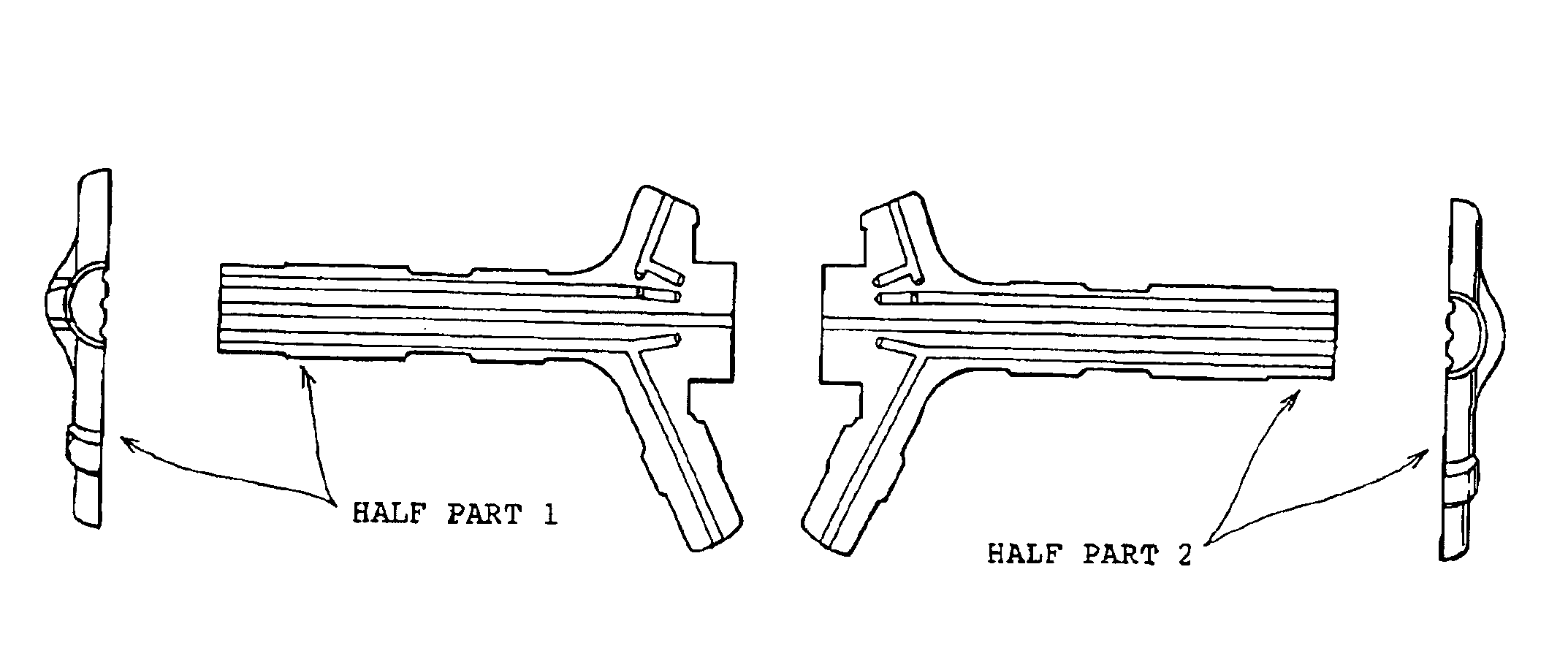
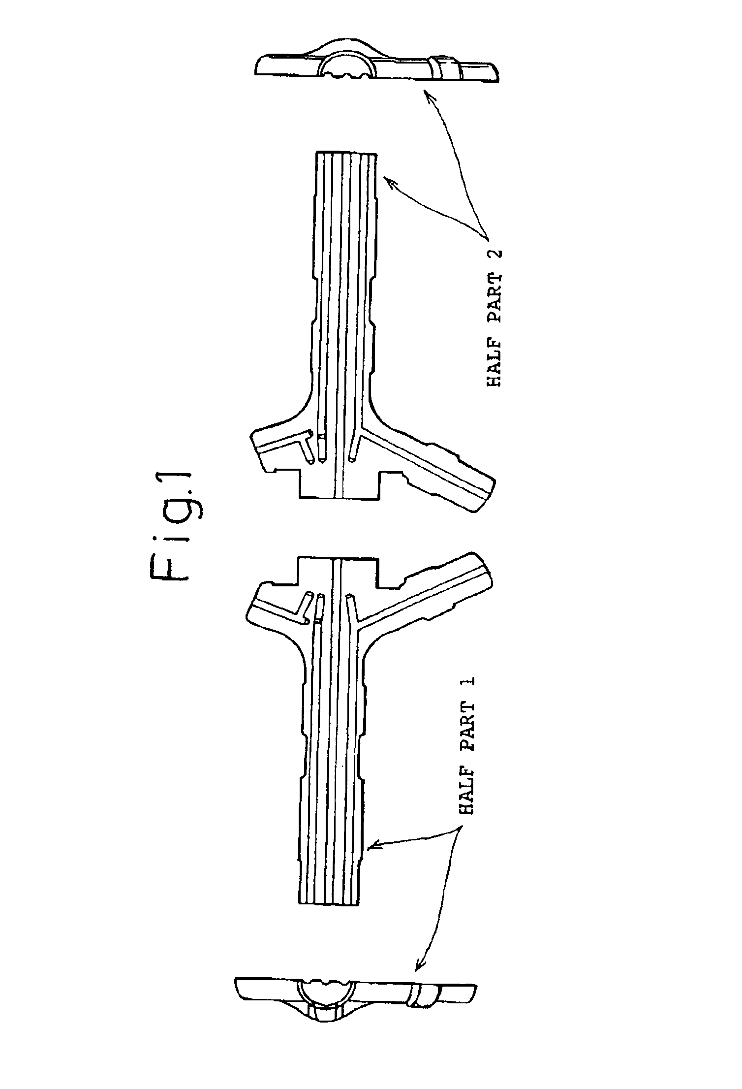
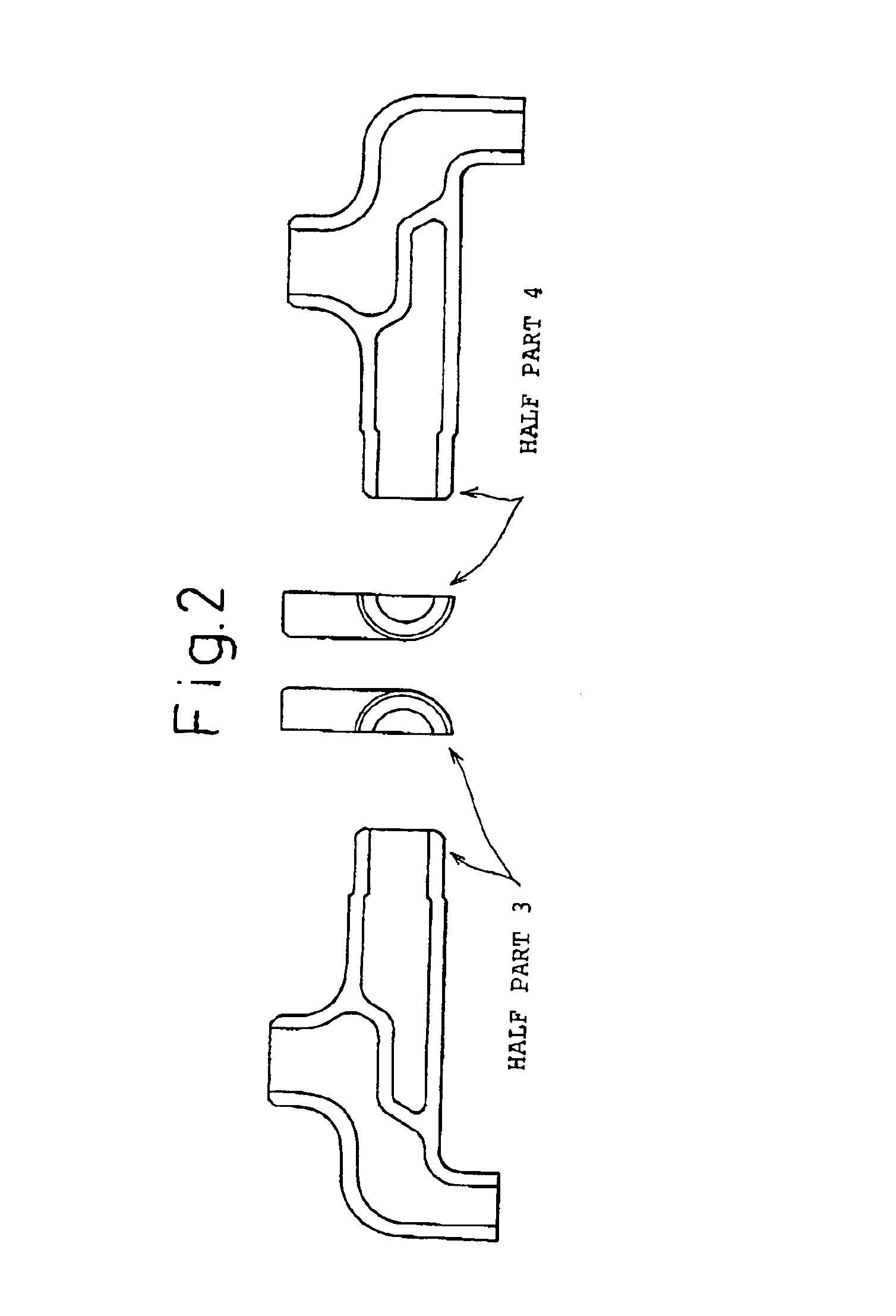
[0063]The half machine parts shown in FIGS. 1 and 2 were butted to each other as shown in FIGS. 3 and 4. Between the butted faces, a piece of alloy foil for transient liquid phase diffusion bonding composed of more than 50% amorphous, which was formed into the same profile of the butted face by cutting or machining, the thickness of which was 30 μm, was interposed. While a sufficiently heavy load for transient liquid phase diffusion bonding was being exerted on the butted faces, the entire machine parts were put into a furnace, in which the atmosphere could be controlled, having a high frequency induction heating coil, and the machine parts were all quickly heated to a transient liquid phase diffusion bonding temperature and maintained at the temperature for a period of time necessary for isothermal solidification of transient liquid phase diffusion bonding. After that, the entire machine parts were cooled to room temperature and finished to a final profile as shown in FIG. 5 or 6. ...

example 2

[0074]Bonding alloy foil, the chemical composition of which is described in claims 4, 5 and 7, was selected to be the material for bonding in the form of foil, powder or plating. Steel, the chemical composition of which is shown in Table 2, was interposed between the bonding faces in the case of assembling the half machine part, the profile of which is shown in FIG. 7, so that a sufficiently appropriate profile and a sufficiently large area could be provided. The butted parts were quickly heated to a transient liquid phase diffusion bonding temperature: 900° C. or 1200° C. After that, the butted parts were held at the bonding temperature for 60 to 300 seconds and then cooled. In this way, the product was manufactured. After the completion of assembling bonding, an external surface was finished, as necessary. The part, the profile of which was formed into a final profile, was cut on a face perpendicular to the bonding face with respect to the internal pipe line, and the amount of con...


PUM

PropertyMeasurementUnit
surface pressureaaaaaaaaaa
temperatureaaaaaaaaaa
surface roughnessaaaaaaaaaa

Abstract

A precision machine part is made of a plurality of pieces with a transient liquid phase diffusion bonding alloy provided between the pieces to bond them together. The precision machine part has one or more conveyance passages formed in it, has a longitudinal axis and is configured to permit passage of liquid or gas through the conveyance passage from a pipe line or cylinder. The pieces of the precision machine part are adhered to each other by transient liquid phase bonding with a ribbon of an amorphous bonding alloy. The bonding alloy can contain 1 to 10 atomic % V or can contain 1 to 15 atomic % of B or P or a mixture of B and P and 1 to 10 atomic % V, the balance being Fe and unavoidable impurities, and can exhibit an amount of contraction in a bonding stress loading direction caused by plastic deformation in the bonding process of not more than 5%. The bonding alloy may be an amorphous Ni-based alloy.

Description

BACKGROUND OF THE INVENTION[0001]1. Technical Field of the Invention[0002]The present invention relates to a method of manufacturing machine parts made by means of transient liquid phase diffusion bonding. More particularly, the present invention relates to precision machine parts made of metal by means of transient liquid phase diffusion bonding in the case of assembling machine parts, which have been conventionally manufactured by means of integral molding, having a complicated and precise pipe line inside for conveying a fluid or reducing weight and also having a cylinder inside in which a small sliding member slides.[0003]2. Description of the Background Art[0004]A precision part having a pipe line inside for conveying a fluid and also having a moving path in which a sliding member moves, for example, a moving blade of an internal cooling type turbine, a fuel injection pipe for automobile use, a cylinder head of an internal combustion engine or a faucet used for water supply or ...

Claims


Application Information

Patent Timeline
Patent Type & Authority Patents(United States)
IPC IPC(8): B23K20/16B23K20/18B23K13/01B23K13/00B23K20/02B23K35/30B23K35/00
CPCB23K13/01B23K20/16B23K20/18B23K35/001B23K35/3033B23K35/3093C22C38/002C22C38/02C22C38/04C22C38/12C22C38/14C22C38/18B23K20/023Y10T428/12951B23K35/002B23K35/004B23K35/005Y10T428/12979Y10T428/24562Y10T428/12819Y10T428/24744Y10T428/12937B23K20/00
Inventor HASEGAWA, YASUSHISHINOHARA, YASUHIROTAKAGI, YUTAKA
Owner FUKUJU INDS
Learn More