High frequency power amplifier and wireless communication module

a technology of high frequency power amplifier and wireless communication module, which is applied in the direction of amplifier combinations, amplifier modifications to reduce non-linear distortion, gain control, etc., can solve the problems of poor efficiency at a low output, reduced packaging density, and large circuit scale, so as to improve efficiency and reduce total power consumption , the effect of improving efficiency

Inactive Publication Date: 2005-07-05
MURATA MFG CO LTD
View PDF4 Cites 29 Cited by
  • Summary
  • Abstract
  • Description
  • Claims
  • Application Information

AI Technical Summary

Benefits of technology

[0015]According to the above means, a high frequency power amplifier can be obtained which is capable of improving efficiency at a low output while output's linearity is being ensured. Thus, since the efficiency at a low output relatively high in the frequency of its use is enhanced, the total power consumption is reduced, and a wireless communication apparatus such as a cellular phone or the like using this type of high frequency power amplifier is capable of increasing a call time and the life of a battery used therefor.
[0016]Preferably, the power control circuit, which controls the power supply voltage for each output power FET based on the output level designation signal, makes use of a circuit which comprises an operational amplifier circuit for amplifying the output level designation signal and a MOSFET whose gate is controlled based on the output of the operational amplifier circuit to thereby output a power supply voltage for the output power FETs from a drain thereof and which feeds back the drain voltage of the MOSFET to the operational amplifier circuit to thereby generate a desired power supply voltage. There is further provided a buffer circuit having a bipolar transistor as an active element between the operational amplifier circuit and a gate terminal of the MOSFET which outputs the power supply voltage for the output power FETs. Consequently, a high frequency power amplifier is obtained which improves response to a control signal and is also capable of performing transmission based on an EDGE modulation system for changing a power supply voltage

Problems solved by technology

However, the system for controlling the output power by the APC circuit is accompanied by a problem that a circuit scale becomes large and a packaging density is decreased.
Meanwhile, the conventional high frequency power amplifier of o

Method used


Image

  • High frequency power amplifier and wireless communication module
  • High frequency power amplifier and wireless communication module
  • High frequency power amplifier and wireless communication module

Examples


Embodiment Construction

[0032]Preferred embodiments of the present invention will hereinafter be described in detail with reference to the accompanying drawings. Incidentally, components each having the same function in all drawings for describing the embodiments of the present invention will be described with the same reference numerals.

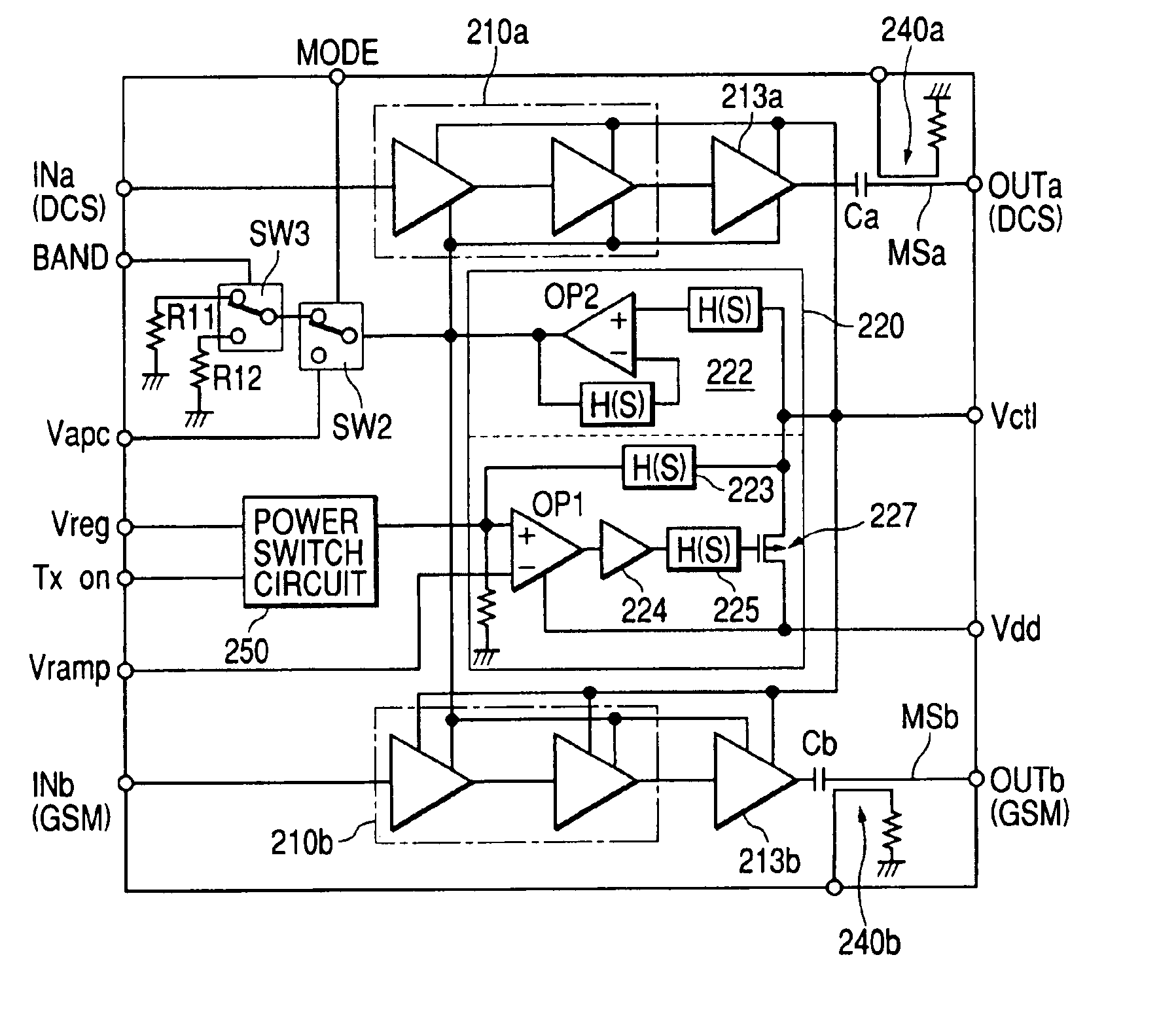
[0033]FIG. 1 shows a schematic configuration of an embodiment illustrative of a high frequency power amplifier according to the present invention. In FIG. 1, reference numeral 210 indicates a high frequency power amplifier, and reference numeral 220 indicates an operating voltage control circuit for generating a voltage to be applied to the high frequency power amplifier 210, respectively. The high frequency power amplifier 210 comprises amplifying stages 211, 212 and 213 corresponding to three stages, and a bias circuit 214 for applying bias voltages Vg1, Vg2 and Vg3 to these amplifying stages respectively. The operating voltage control circuit 220 comprises a power contr...


PUM


Abstract

The present invention provides a high frequency power amplifier of an open-loop type, which outputs a signal having a level corresponding to an output level required under control of a power supply voltage for each output power FET, based on a control signal for the output level. The high frequency power amplifier is provided with a bias voltage generating circuit which generates a gate bias voltage of each output power FET according to an output voltage of a power control circuit for controlling the power supply voltage for the output power FET, based on the control signal for the output level.

Description

[0001]This is a continuation application of U.S. Ser. No. 10 / 294,597, filed on Nov. 15, 2002, now U.S. Pat. No. 6,753,735. This application is related to U.S. Ser. No. 10 / 337,819, filed on Jan. 8, 2003, now U.S. Pat. No. 6,741,125.BACKGROUND OF THE INVENTION[0002]The present invention relates to a high frequency power amplifier and a technology effective for application to a wireless communication apparatus such as a cellular phone or the like with the high frequency power amplifier built therein, and particularly to a technology for speeding up an open-loop type high frequency power amplifier capable of controlling a power supply voltage for output power FETs constituting the high frequency power amplifier to thereby control output power and improving efficiency thereof at a low output.[0003]An output section on the transmitting side of a wireless communication apparatus (mobile communication apparatus) such as a mobile phone, a cellular phone or the like has built therein a module...

Claims


Application Information

Patent Timeline
IPC IPC(8): H03G3/00H03G3/30H03F3/213H03F1/32H04B1/04
CPCH03G3/004H03G3/3042H03G3/3047H01L2224/48091H01L2224/48227H01L2924/19105H01L2924/13091H01L2924/00014H01L2924/00
Inventor ARAI, SATOSHISHIBUYA, TSUYOSHISEKIGUCHI, HITOSHIMATSUDAIRA, NOBUHIROFURUYA, TOMIOMARUYAMA, MASASHIOHYAMA, YASUSHI
Owner MURATA MFG CO LTD
Why Eureka
Try Eureka