Multiple frequency grain moisture sensor for combines

a moisture sensor and multi-frequency technology, applied in the field of grain moisture sensors, can solve the problems of inoperable moisture sensor, lag time or delay, inaccurate readings, etc., and achieve the effect of reducing fringe effects, uniform electric field density, and equal sensitivity to grain

Inactive Publication Date: 2005-07-12
DEERE & CO
View PDF24 Cites 13 Cited by
  • Summary
  • Abstract
  • Description
  • Claims
  • Application Information

AI Technical Summary

Benefits of technology

[0027]A still further object of the present invention is to provide a grain moisture sensor that provides for the measurement of complex permittivity of the grain.
[0028]Another object of the present invention is to provide a grain moisture sensor that provides for the measurement of complex permittivity of the grain at more than one frequency.
[0029]A grain moisture sensor of the present invention provides for the sensing of the moisture of grain being harvested by a combine. One aspect of the present invention relates to the location of the grain moisture sensor on the combine. According to the present invention, the grain moisture sensor is mounted off of the front of the clean grain elevator transition housing inside of the grain tank. This provides the advantages of access to the grain moisture sensor if required and the advantage that all leaks are contained. A further advantage is that the grain moisture sensor fills positively with grain. Further, this location of the grain moisture sensor allows for the sensor to always be filled regardless of the slope conditions of the combine.
[0030]Another aspect of the present invention relates to the cell design of the sensor. The cell of the present invention includes a driven plate to which excitation voltages are applied, a sense plate proximate and parallel to the driven plate for measuring current that passes through the cell, a fill plate adjacent to the sense plate for determining when the cell is full, and a guard adjacent to the sense plate and the fill plate for protecting the sense plate and the fill plate. The guard is electrically isolated from, but at the same potential as a sensed plate. The guard is parallel to and dimensionally larger than the sense plate in order to shape the electric field. The presence of the guard plate provides the advantage of straight electric field lines perpendicular to the sense plate and of uniform density throughout the region between the parallel plates. This results in reduced fringe effects and uniform electric field density allowing ...

Problems solved by technology

There are a number of problems with mounting the moisture sensor in this location.
If the moisture sensor is not kept clean,readings may be inaccurate or the moisture sensor may be inoperable.
A further problem with mounting the moisture sensor in the loading auger of a combine is the lag time or delay encountered when measuring moisture.
This deficiency frustrates the use of a moisture sensor in precision agriculture applications, making it more difficult to correctly associate a particular field location with a particular grain moisture.
A further problem with mounting grain moisture sensors in a loading auger is that such a moisture system does not provide for determining when there is sufficient grain present for a grain moisture measurement.
A moisture sensor that is not filled with grain is not accurately measuring the moisture of the grain.
Therefore, this inability to know when the capacitive plate is covered can result in erroneous grain moisture measurements.
Despite these improvements, a number of problems remain with mounting a moisture sensor on the side of the clean grain elevator in a combine.
One problem relates to the slow cycle time of the moisture sensor.
In a low flow condition which is not uncommon in grain harvesting, the sensor can be extremely slow to fill.
For example, it may take up to four minutes to fill the sensor.
Therefore, the number of moisture sensor readings is reduced and the moisture sensor data is insufficient for providing accurate measurements for moisture maps, yield determinations, and other purposes.
A further problem with mounting moisture sensors on the side of the clean grain elevator relates to the sensitivity of this mounting location in the presence of side slopes.
When the combine is operated on a slope such that the grain flow is directed away f...

Method used


Image

  • Multiple frequency grain moisture sensor for combines
  • Multiple frequency grain moisture sensor for combines
  • Multiple frequency grain moisture sensor for combines

Examples


Embodiment Construction

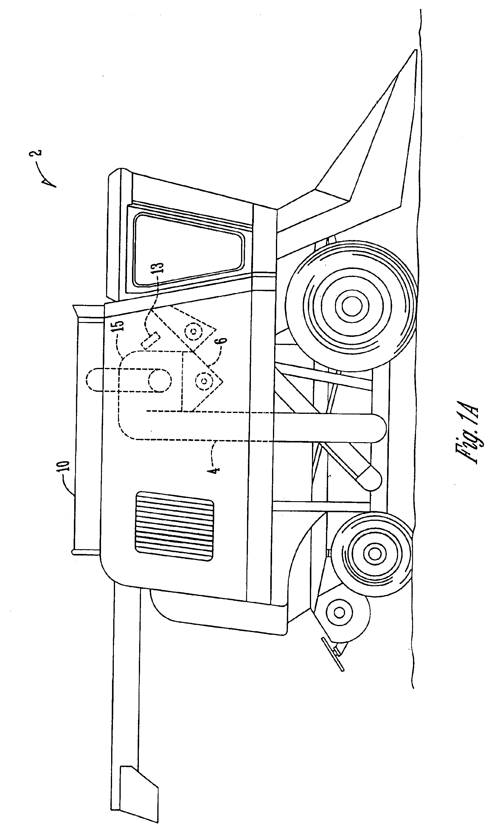
[0041]FIG. 1A shows a combine having a grain moisture sensor according to the present invention. In FIG. 1A, the combine 2 is shown with a grain tank 10. In addition, the clean grain elevator 4 is shown. Grain from the clean grain elevator 4 travels to the transition housing 15 of the grain tank 10. The sump 6 of the transition housing is also shown.

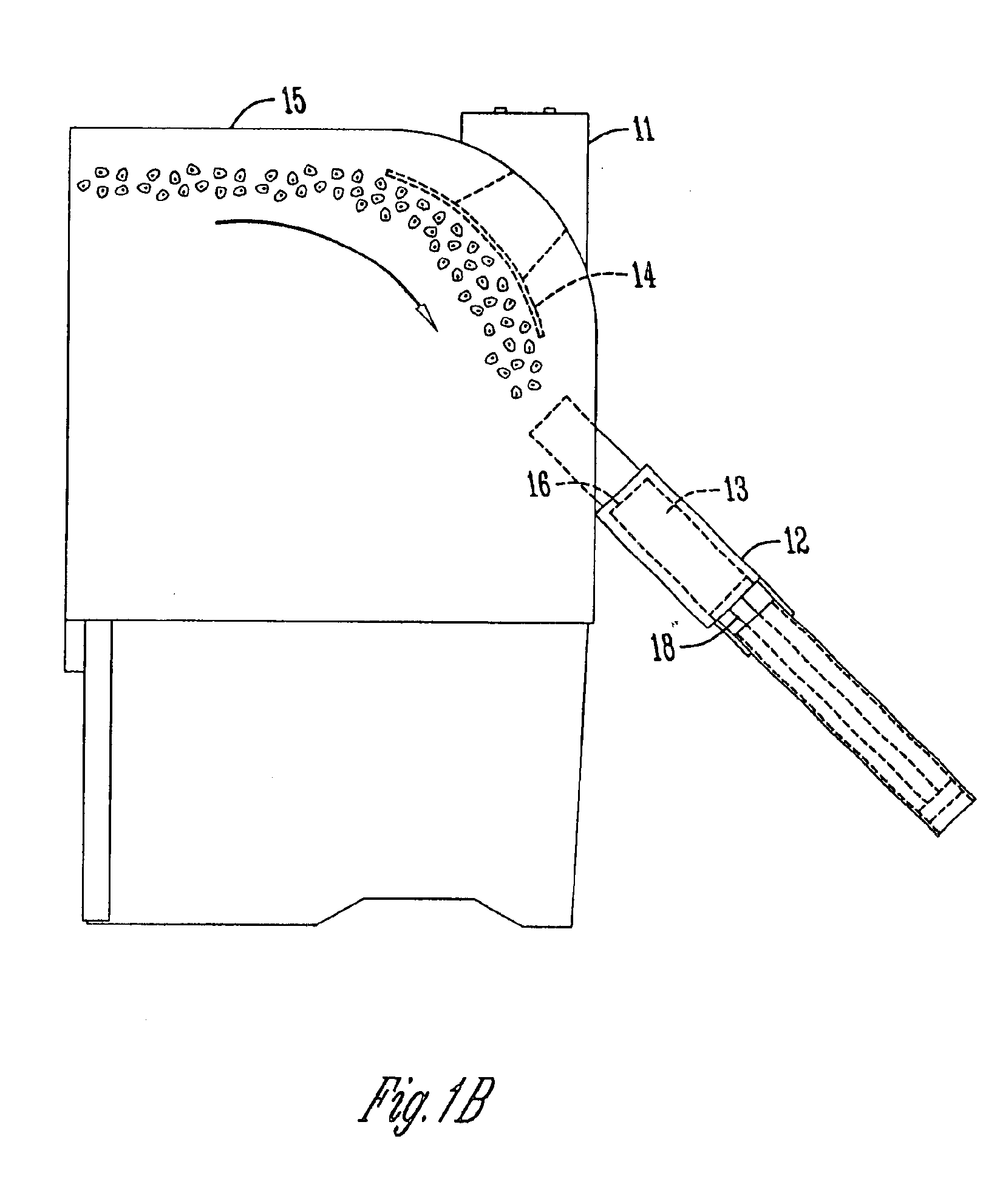
[0042]FIGS. 1B and 1C show side views of the grain moisture sensor of the present invention as mounted in a combine. The grain tank 10 shown includes the grain moisture sensor 12. The grain moisture sensor 12 is located in the grain tank 10 of the combine near the mass flow sensor 11. The cell opening 16 is located below the impact plate 14 in the transition housing 15. Although an impact plate 14 is shown, the present invention contemplates that other deflectors can be used. In this location, the cell 13 is positively filled due to the direct or indirect velocities of grain created from the clean grain elevator paddles (not shown). This...


PUM


Abstract

A grain moisture sensor having a sensor cell that includes a driven plate, a sense plate proximate to and substantially parallel with the driven plate for capacitive measurement across a spacing between the driven plate and the sense plate, and a fill plate adjacent the sense plate and substantially parallel with the driven plate for sensing whether the spacing is filled with grain. The grain moisture sensor provides for measuring real and imaginary components of an excitation voltage applied to the driven plate, measuring real and imaginary components of a sense current sensed at the sense plate, calculating a complex admittance of the cell, calculating a complex admittance of a reference admittance, and calculating a grain complex permittivity.

Description

CROSS REFERENCE TO A RELATED APPLICATION[0001]This application is a division of U.S. Ser. No. 10 / 003,884 filed Oct. 25, 2001 now U.S. Pat. No. 6,686,749.BACKGROUND OF THE INVENTION[0002]1) Field of the Invention[0003]The present invention relates generally to grain moisture sensors. More specifically, the present invention relates to an improved grain moisture sensor for combines.[0004]2) Related Art[0005]Grain moisture sensors have been used in combines, particularly in precision agriculture applications. Continuous or instantaneous grain moisture readings allow an operator to observe the moisture of the grain as it is being harvested. In conjunction with a GPS unit, a moisture sensor can be used to provide moisture mapping. In addition, moisture sensors are used in yield monitoring applications. When used in combination with a grain flow sensor, the moisture sensor information is often used to calculate the number of dry bushels in a field and the number of bushels per acre based ...

Claims


Application Information

Patent Timeline
IPC IPC(8): A01D41/00A01D41/127A01D41/12G01N27/22G01N33/02G01N33/10G01R27/08
CPCA01D41/1208A01D41/1277G01N27/223G01N33/02G01N33/10
Inventor RAINS, GERALD E.PHELAN, JAMES J.SLAVENS, ZACHARY W.KOZICKI, ANDRZEJFUNK, ROBERT C.
Owner DEERE & CO
Why Eureka
Try Eureka