Actuator for workpiece holding device

a technology of workpiece holding and actuator, which is applied in the direction of turning apparatus, metal-working holder, support, etc., can solve the problems of increased power consumption due mainly to oil shearing, mechanical failure, and increased parts and expenses, and achieves large mechanical advantage, large mechanical advantage, and saving cycle time

Inactive Publication Date: 2005-07-19
PRATT BURNERD INT
View PDF8 Cites 14 Cited by
  • Summary
  • Abstract
  • Description
  • Claims
  • Application Information

AI Technical Summary

Benefits of technology

[0018]Thus, in the present invention the grip of the jaws on the work piece is controlled by position or by force, or by a combination of both position and force. Position is determined from the angular displacement of the pulley relative to the spindle, and force is determined from the applied torque or alternatively strain measurement as described hereinafter. This removes the possibility of workpiece distortion which is a common problem with conventional, hydraulically operated power chucks, hence saving cycle time because the jaws are moved only to the extent required.
[0019]The jackscrew may comprise a single, threaded cylinder, or alternatively may comprise a number (typically 3) of individual screws arranged around and equally spaced on a pitch circle, the latter being more efficient. A third option is to have two concentric screws (differential screws) of slightly different pitch, to provide a large mechanical advantage.
[0020]The jackscrew may comprise two concentric screws (differential screws) at slightly different pitch, which may provide a large mechanical advantage.
[0021]The jackscrew may comprise a single threaded cylinder with at least three or more planetary threaded rollers arranged around and equally spaced on a pitch circle, the threaded rollers roll (rather than slide). Such an arrangement offers considerably less resistance making the jackscrew more efficient.

Problems solved by technology

This conventional power chucking system suffers from a number of disadvantages, including those arising from the fact that a separate power source is required to drive the rotating cylinder (chuck actuator), namely increased numbers of parts and expense, and increased power consumption due mainly to shearing of oil as the cylinder rotates.
Also, the pressure of the rotating cylinder is manually adjusted and can be adjusted to pressures well in excess of the chuck capabilities, which can result in mechanical failure.
Other disadvantages include grip hysteresis resulting from stopping a chuck rotating at speed and then starting it again, which can lead to an increase in grip and hence distortion of the workpiece, the safety requirement for additional sensors to detect when the cylinder is near the end of the stroke, and possible loss of grip in the event of loss by pressure to the cylinder.

Method used


Image

  • Actuator for workpiece holding device
  • Actuator for workpiece holding device
  • Actuator for workpiece holding device

Examples


Embodiment Construction

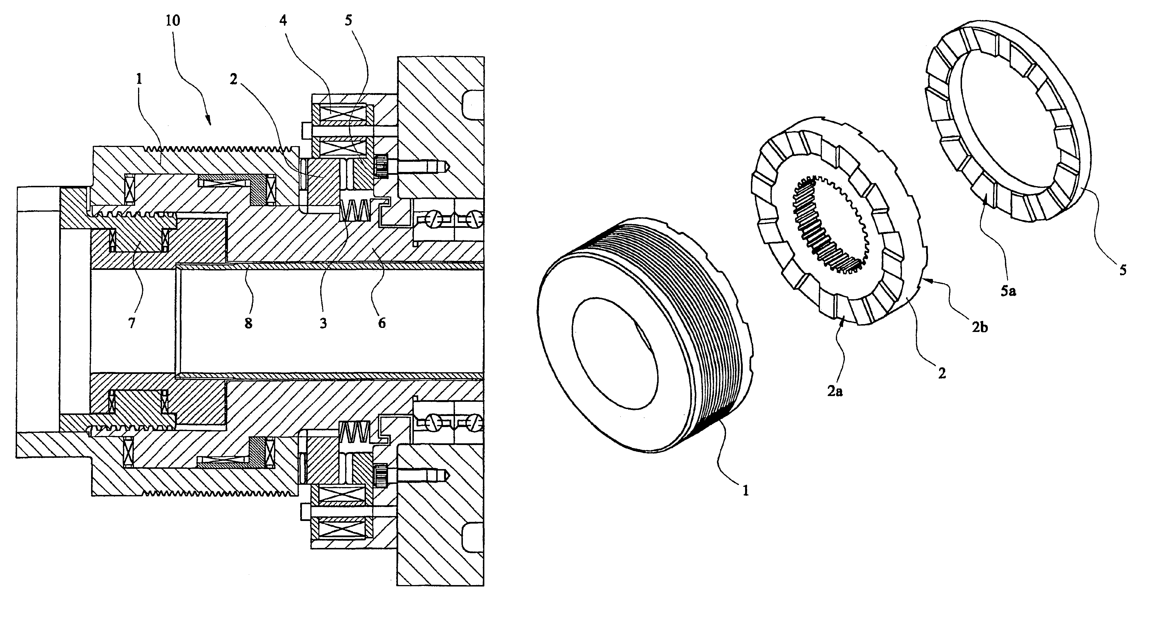
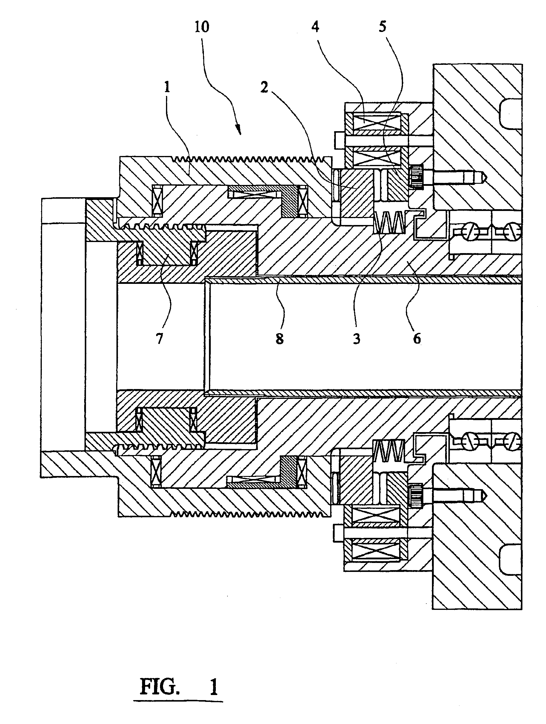
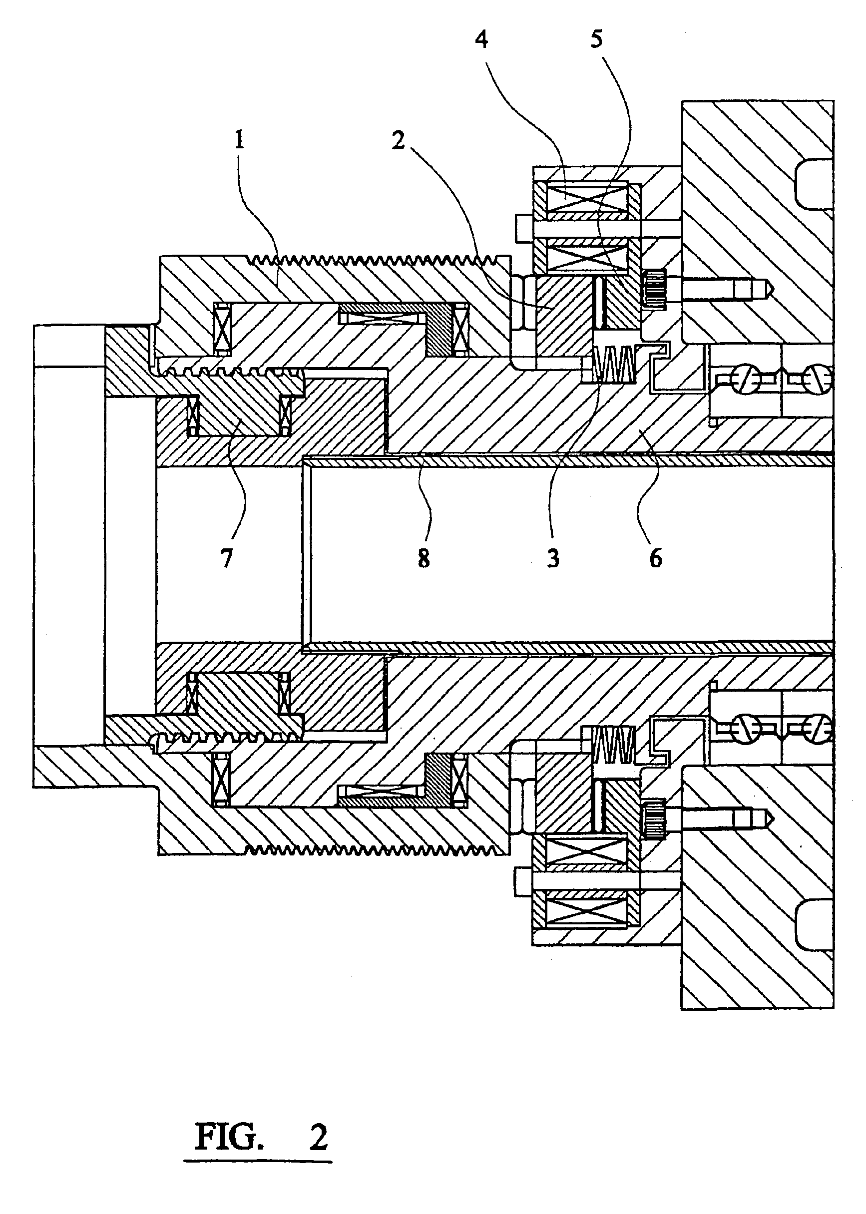
[0041]Referring to the drawings, in FIG. 1 a power chucking system 10 according to the present invention comprises a chuck mounted on a headstock, the chuck with its jaws (not shown) being caused to rotate by rotation of machine spindle 6. In normal operation, the drive pulley 1 by means of which the machine drive is transmitted to the spindle 6, is locked to the spindle by means of a face tooth coupling (clutch) 2 which is pushed by spring 3 into engagement with pulley 1.

[0042]Actuation of the jaws of the chuck is effected by rotation of actuator jack 7 which is connected to the chuck via drawtube 8.

[0043]Whereas in conventional power chucking systems a separately powered (pneumatic or hydraulic) rotating cylinder is mounted on the drive pulley 1 in order to actuate the chuck jaws, in the present invention the chuck s is actuated using the same machine drive as rotates the spindle, i.e. the lathe spindle prime mover drive. This is achieved by a solenoid 4 (or hydraulic means, for e...


PUM

PropertyMeasurementUnit
hydraulic poweraaaaaaaaaa
hydraulic pressureaaaaaaaaaa
pressureaaaaaaaaaa

Abstract

A power chucking system 10 comprises a chuck mounted on a headstock, the chuck with its jaws being caused to rotate by rotation or the machine spindle 6. The spindle 6 may be engaged with the pulley 1 in order to rotate a work piece retained within the chuck jaws. A clutch 2 may be used to disengage the spindle 6 from the pulley 1 and to lock the spindle 6 to the head stock. In this configuration, rotation of the pulley 1 will cause an actuator jack 7 to screw or unscrew, into or out of spindle 6, in order to open or close the chuck jaws to grip release the workpiece.

Description

FIELD OF THE INVENTION[0001]The present invention relates to chucking systems, particularly although not exclusively to the type of system having a chuck with jaws for holding the workpiece which is caused to rotate by applying the machine drive via a spindle drive pulley, to a spindle which passes through the headstock of the machine. Such chucking systems may be, for example, an international wedge chuck or a scroll chuck, and the invention relates in particular (but not exclusively) to either or both of these two types of chuck.BACKGROUND OF THE INVENTION[0002]In order to open and close the chuck jaws of a powered chuck, a rotating cylinder is mounted to the spindle drive pulley, and this cylinder rotates with the spindle. In a conventional power chucking system hydraulic power is supplied to drive the cylinder axially, and this axial movement of the cylinder is transmitted to the chuck by means of a rod or tube called a “drawbar” or “drawtube”. Thus, the grip of the jaws on the ...

Claims


Application Information

Patent Timeline
Patent Type & Authority Patents(United States)
IPC IPC(8): B23B31/163B23B31/12B23B31/26
CPCB23B31/16037B23B2260/044B23B2270/38Y10T279/12Y10T82/26Y10T82/2552B23B2270/483
Inventor AYRTON, GLENN DONALD
Owner PRATT BURNERD INT
Why Eureka
Try Eureka