Brittle object cutting apparatus and cutting method thereof

a cutting apparatus and brittle object technology, applied in the direction of laser beam welding apparatus, welding/soldering/cutting articles, basic electric elements, etc., can solve the problems of complex apparatuses, notch creation relatively slowly, and potential microscopic contamination of the material being processed by any volume of removed material, so as to improve efficiency, improve the edge quality of brittle objects, and save the cycle time of moving the brittle object.

Inactive Publication Date: 2016-10-27
NANOPLUS LTD
View PDF3 Cites 1 Cited by
  • Summary
  • Abstract
  • Description
  • Claims
  • Application Information

AI Technical Summary

Benefits of technology

[0024](1) The brittle object cutting apparatus and method thereof simultaneously perform the processes of scribing, heating and cooling, thereby enhancing the edge quality of the brittle objects.
[0025](2) The brittle object cutting apparatus and method thereof set up the heating laser at lateral sides of the scribing laser, such that the heating laser located behind the scribing laser during the machining process, i.e. the brittle objects are irradiated with the scribing laser followed by the heating laser in both forward and reverse direction without rotating the brittle object, thereby saving cycle time of moving the brittle object and further improving efficiency.
[0026](3) The brittle object cutting apparatus and method thereof are provided with the first light guide unit and the second light guide unit so as to form the first heating laser and the second heating laser, separately, thereby reducing the amount of heating laser units and saving cost.

Problems solved by technology

It is disadvantageous that every volume of removed material potentially contributes to the microscopic contamination of the material being processed.
Since the aspect ratio between notch width and notch depth is critical to all these laser processes, complex apparatuses are needed and the notch is created relatively slowly.
Deep notches for thick wafers therefore require increasingly more process time.
Therefore fracture flaws can occur if the breakage lines do not run perpendicular to the material thickness or if two breakage lines intersecting at one point do not meet one another at the intended angle.
In addition, material particles split off, which can entail a macroscopic contamination of the surface of the flat material.
It is disadvantageous particularly if a flat material separated into several parallel strips is to be cut in a second axis, for example, orthogonally to the first separation direction, for example, into individual rectangles in the dicing of a wafer into individual chips.
Since a new initial crack must be made at the beginning of each dividing line in the first separation direction, the process is very time-consuming and the mechanical scoring system is subject to high wear.
Thus, the affected points on the brittle flat materials may be shifted between the two processes, leading to problems such as the breakage lines do not run perpendicular to the material thickness.
Therefore, it is a primary issue to provide a brittle object cutting apparatus and method thereof for cutting a brittle object to solve the above mentioned flaws.

Method used


Image

  • Brittle object cutting apparatus and cutting method thereof
  • Brittle object cutting apparatus and cutting method thereof
  • Brittle object cutting apparatus and cutting method thereof

Examples


first embodiment

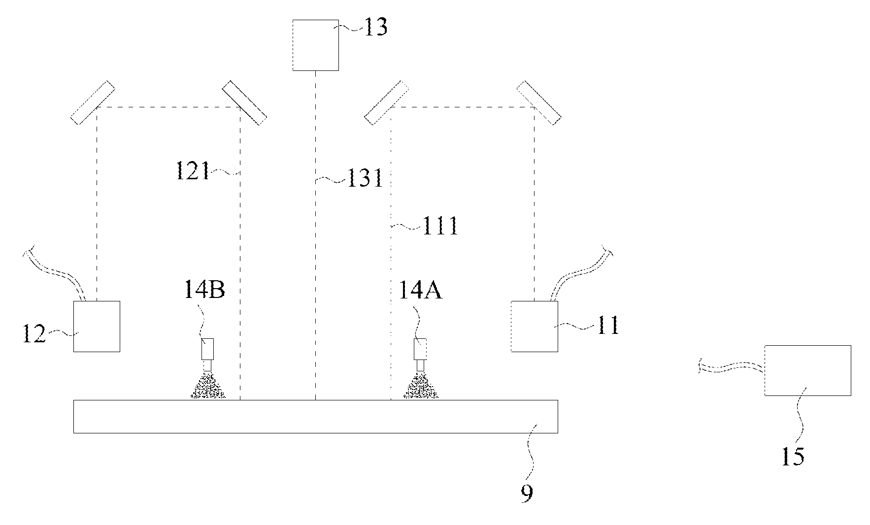
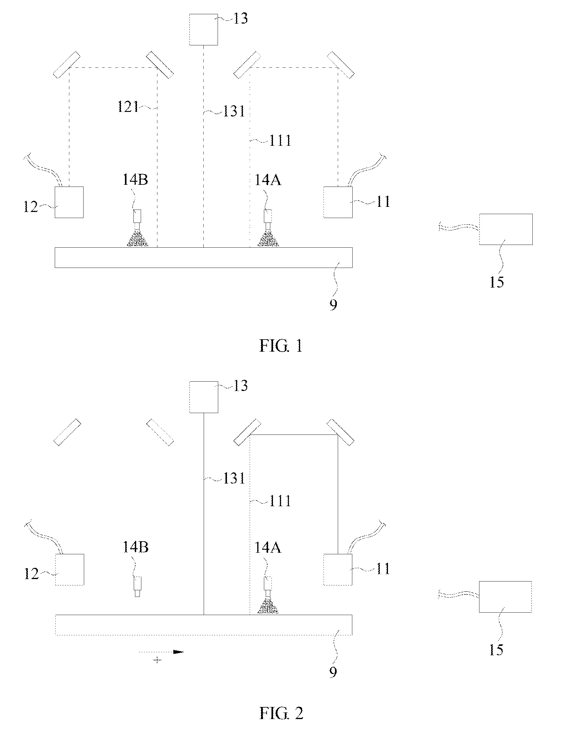
[0040]With reference to FIG. 1 for a structurally schematic view of the brittle object cutting apparatus according to the present invention, the brittle object cutting apparatus for cutting a brittle object comprises a first heating laser unit 11, a second heating laser unit 12, a scribing laser unit 13, two cooling units 14A and 14B, and a processing module 15. The first heating laser unit 11 and the second heating laser unit 12 may be a CO2 laser, and the first heating laser unit 11 may emit a first heating laser 111 and the second heating laser unit 12 may emit a second heating laser 121. The scribing laser unit 13 may be a UV laser, and the scribing laser unit 13 may emit a scribing laser 131 on the brittle object 9, wherein the first heating laser 111 and the second heating laser 121 respectively located on opposite sides of the scribing laser 131 when the first heating laser 111, the second heating laser 121 and the scribing laser 131 are emitted on the brittle object 9. That ...

second embodiment

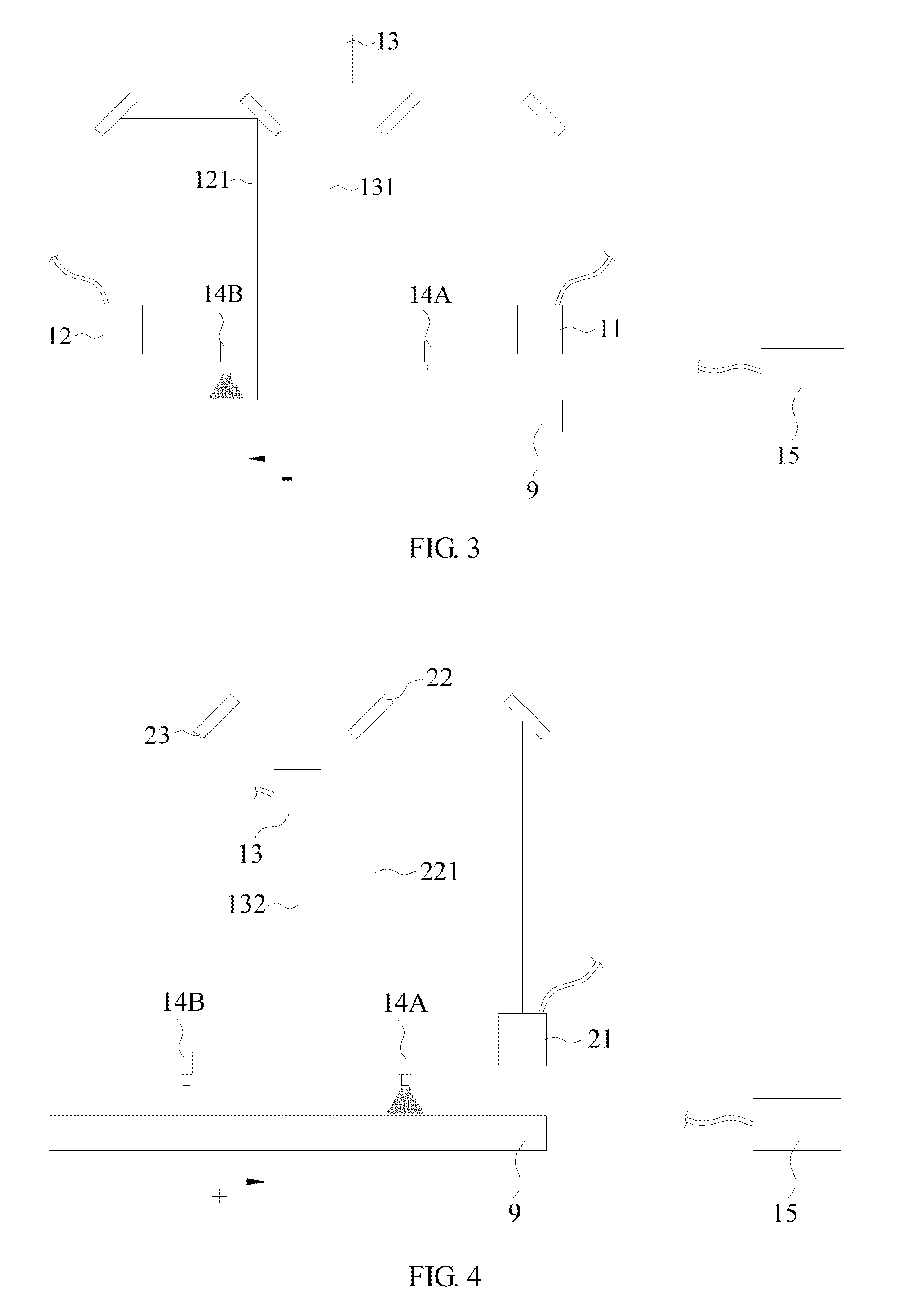
[0045]With reference to FIGS. 4 and 5 for a schematic view of the first aspect and the second aspect in the brittle object cutting apparatus according to the present invention, in the instant embodiment, the brittle object cutting apparatus comprises a heating laser unit 21, a first light guide unit 22, a second light guide unit 23, a scribing laser unit 13, two cooling units 14A, 14B and a processing module 15. The heating laser unit 21 may emit a heating laser. The first light guide unit 22 may be movable reflective mirror, or the first light guide unit 22 may be a splitter. Wherein, the detailed description of the first light guide unit 22 being embodied as splitter will be further described in the next embodiment. Particularly, the first light guide unit 22 guides the heating laser to heat the brittle object 9 via a first optical path 221 or to pass the laser radiation to the second light guide unit 23 when the first light guide unit 22 is moved aside. The second light guide uni...

third embodiment

[0048]Please refer to FIGS. 6 and 7 for a schematic view of the first aspect and the second aspect in the brittle object cutting apparatus according to the present invention. In the instant embodiment, the first light guide unit 22 is embodied as a splitter. In a preferred embodiment, the transmittance and reflectance of the splitter are 50% and 50%, respectively. However, the transmittance and reflectance of the splitter may be varied depending on the machining process or the configuration designed by designers. For instance, the transmittance and reflectance of the splitter may respectively be 40% and 60%, 30% and 70%, etc.

[0049]In the present embodiment, the configuration of the components in the apparatus is similar to the previous embodiment and will not be further described herein. However, it should be noted that there's a movable blocking unit 24 in both the first heating optical path 221 and the second heating optical path 231, respectively. The movable blocking units 24 se...


PUM

PropertyMeasurementUnit
reflectanceaaaaaaaaaa

Abstract

A brittle object cutting apparatus and the method thereof are disclosed. Wherein, the brittle object cutting apparatus comprises a first heating laser unit, a second heating laser unit, a scribing laser unit, two cooling units and a processing module. A heating laser from the heating laser units respectively located on opposite sides of a scribing laser from the scribing laser unit, and a coolant of the cooling unit followed behind the heating laser. In the moving process of the brittle object, the processing module controls the scribing laser for a scribing operation, and controls one of the heating lasers and the coolant form one of the cooling units to heat and cool the brittle object. As a result, the machining time of dicing the brittle objects may be effectively reduced.

Description

BACKGROUND OF THE INVENTION[0001]1. Field of the Invention[0002]The present invention relates to a cutting apparatus and cutting method thereof, in particular to a brittle object cutting apparatus and cutting method thereof, which apply laser to generate thermally-induced mechanical stress in order to cut brittle objects.[0003]2. Description of the Related Art[0004]Cutting brittle materials such as glass, sapphire, silicon, gallium arsenide or ceramics by producing a notch along the desired dividing line, along which breaking stresses are subsequently produced by subjection to mechanical forces, which leads to the complete separation of the brittle material, is already known.[0005]In order to cut the brittle material in this way, the depth of the notch must be at least one-third of the flat material thickness. The notch can be applied mechanically or by means of lasers. Particularly for dicing chips from substrates (wafers), laser methods that create a notch by ablation into the mat...

Claims


Application Information

Patent Timeline
Patent Type & Authority Applications(United States)
IPC IPC(8): B23K26/364B26F3/06B23K26/402
CPCB23K26/364B23K26/402B23K2203/56B23K2203/52B23K2203/54B26F3/06B23K26/0604B23K26/14B23K26/38B23K26/703B23K2101/40B23K2103/50B23K2103/52B23K2103/54B23K2103/56
Inventor LU, HUNG-TUKONDRATENKO, VLADIMIRNAUMOV, ALEXANDERHSU, CHIH-PENGHSU, WEI-NUNG
Owner NANOPLUS LTD
Why Eureka
Try Eureka