Microstructure drying treatment method and its apparatus and its high pressure vessel

a drying treatment method and microstructure technology, applied in lighting and heating apparatus, photosensitive material processing, furnaces, etc., can solve the problems of pattern collapse, long treatment time of conventional critical point drying method, pattern collapse, etc., to minimize the amount of rinsing liquid, reduce the effect of even a reduction in solubility and high substitution efficiency

Inactive Publication Date: 2005-07-26
HITACHI SCI SYST LTD
View PDF11 Cites 12 Cited by
  • Summary
  • Abstract
  • Description
  • Claims
  • Application Information

AI Technical Summary

Benefits of technology

[0011]The object of the present invention is to provide a microstructure drying treatment method that can dry a microstructure substrate uniformly and in a short time without generating pattern collapse, and its apparatus and its high pressure vessel.
[0014]Further, desirably, in the present invention, the fluid should be a liquid and be compression-transported to the high pressure vessel by a high pressure pump, and then the collected rinsing liquid is drained to the outside of the high pressure vessel from at least one of outlets provided on the top and bottom of the high pressure vessel. Still more, desirably, the convection of the fluid nearby the substrate should be prevented by adjusting at least one of temperatures at the upper and lower sides of the substrate and eliminating a temperature difference on the upper and lower sides of the substrate. Similarly, desirably, after the fluid is introduced into the high pressure vessel and predetermined pressure is reached, a rinsing liquid should be collected by stopping the introduction of the fluid and halting a flow of the fluid inside the high pressure vessel through a step of holding a predetermined pressure state.
[0018]Further, the microstructure drying treatment apparatus of the present invention is provided with a high pressure pump which compression-transports a fluid to a high pressure vessel to supply a sufficient fluid to dissolve a rinsing liquid inside a high pressure vessel. Further, the apparatus has a control means performs a substitution process that reduces a flow rate at which a substitution fluid is compression-transported by a high pressure pump to zero and minimizes, that is, reduces the speed of the substitution fluid inside the high pressure vessel to zero to converge and collect the turbidity of the substitution fluid and the rinsing liquid that occurs to no small extent when the substitution fluid is introduced.
[0019]Still more, the microstructure drying treatment apparatus of the present invention can drain a rinsing liquid that is not dissolved in a fluid selectively by providing at least an outlet on the top and bottom of a high pressure vessel even when two or more types of a rinsing liquid having a higher specific gravity than a substitution fluid and a rinsing liquid having a lower specific gravity than the substitution fluid are used. Further, the apparatus can minimize the conviction of the rinsing liquid and the substitution fluid in a turbid state, and converge and collect the turbid state in a short time by providing a thermoregulator at the upper and the lower sides of a substrate.
[0022]As described above, the present invention introduces a fluid such as carbon dioxide, that is gas at normal temperature and pressure and is liquid under high pressure, in a liquid state as a substitution solvent of a rinsing liquid into a high pressure vessel that works as a drying treatment chamber in which a sample having a microstructure, such as a resist substrate, after exposure, development, and rinsing is installed. In resist drying treatment that utilizes the substitution effect of the rinsing liquid caused by the solubility of the fluid that is introduced in the liquid state, the present invention can minimize the amount of the rinsing liquid that is left in the high pressure vessel by changing temperature and pressure, controlling the specific gravity of a substitution fluid, collecting the rinsing liquid that is not dissolved in the fluid at the upper or lower side, and draining the rinsing liquid to the outside of the high pressure vessel selectively. Further, because the present invention can maintain the density of the substitution fluid relative to the rinsing liquid to the minimum, it can minimize even a reduction in solubility, and obtain high substitution efficiency and shorten a substitution process by suppressing the reduction of the solubility to the rinsing liquid that is left between the microstructures.
[0023]As a result, the present invention can solve a defect of a conventional critical point drying method that this drying treatment time is long and a defect that a uniform drying result cannot be obtained for a large-caliber substrate. The present invention can dry, uniformly without generating pattern collapse, such a substrate that has a microstructure of a resist to fabricate an LSI on a large scale, a microstructure of a pattern width of less than 70 nm, in particular, a pattern width of less than 30 nm and a diameter of 100 mm or more. The present invention can provide such a treatment speed that it is applied to a device production line.

Problems solved by technology

In a conventional drying process, however, when the dimensions, that is, the width of space between patterns formed on a resist substrate amounts to less than about 90 nm, Laplace force operates between the patterns by the surface tension (capillarity) of a fluid that is left between the patterns, and pattern collapse occurred.
Still more, if pattern width scales down and amounts to less than about 70 nm even in the drying process that uses a supercritical fluid and a low surface tension rinsing liquid, the pattern collapse cannot be prevented.
Further, a conventional critical point drying method is long in treatment time and requires the time from about several ten minutes to one hour or more.
Because a large-diameter substrate having a diameter of 100 mm or more, especially a pattern of less than about 40 nm, is exceedingly inferior in the substitution efficiency of a rinsing liquid and liquid carbon dioxide.
Accordingly, because the rinsing liquid that is left between patterns cannot be substituted even if the substitution time of about three hours is set, the surface tension operates between the patterns and pattern collapse can hardly be prevented.
Further, the large-caliber substrate could not be dried uniformly.

Method used


Image

  • Microstructure drying treatment method and its apparatus and its high pressure vessel
  • Microstructure drying treatment method and its apparatus and its high pressure vessel
  • Microstructure drying treatment method and its apparatus and its high pressure vessel

Examples


first embodiment

[0037

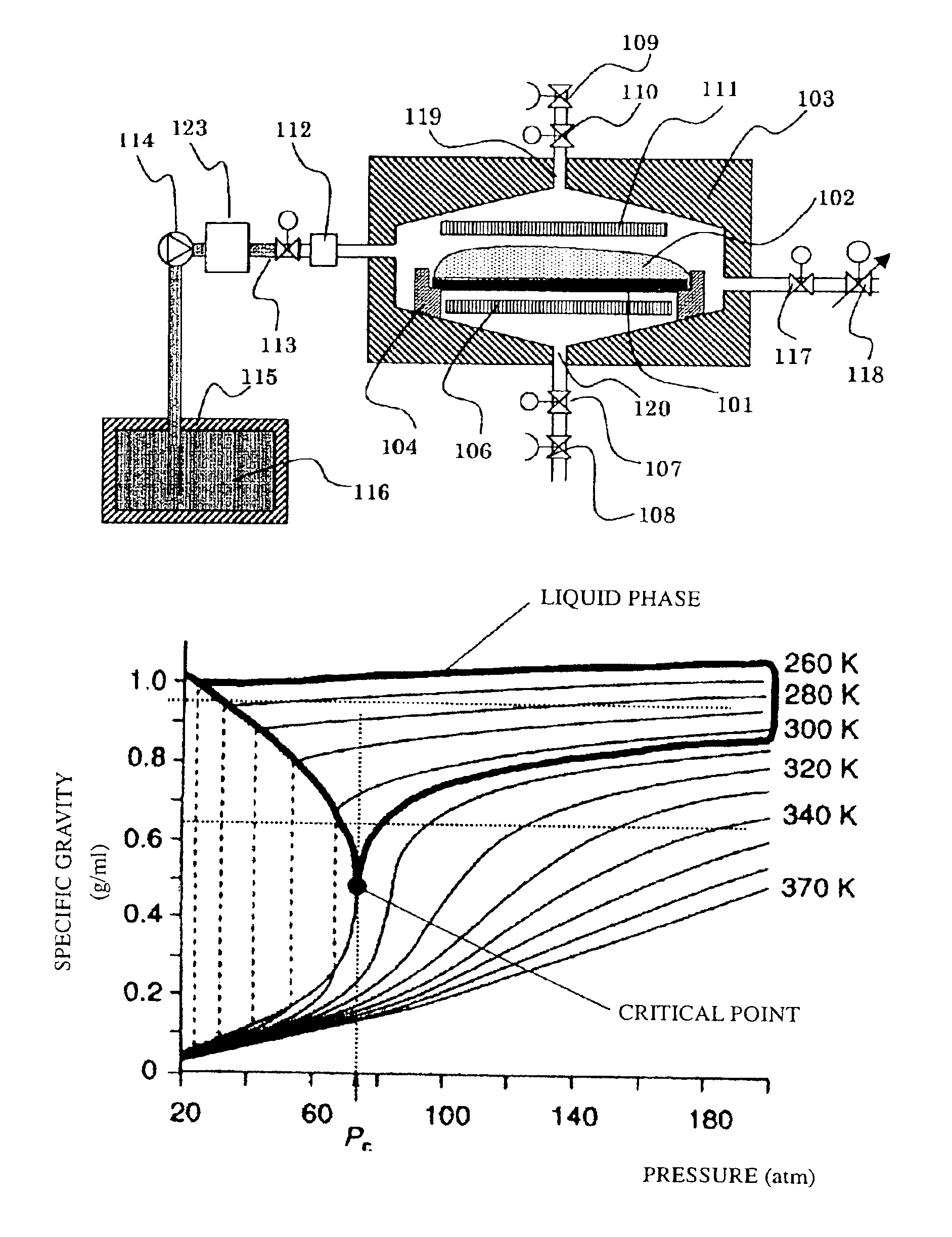
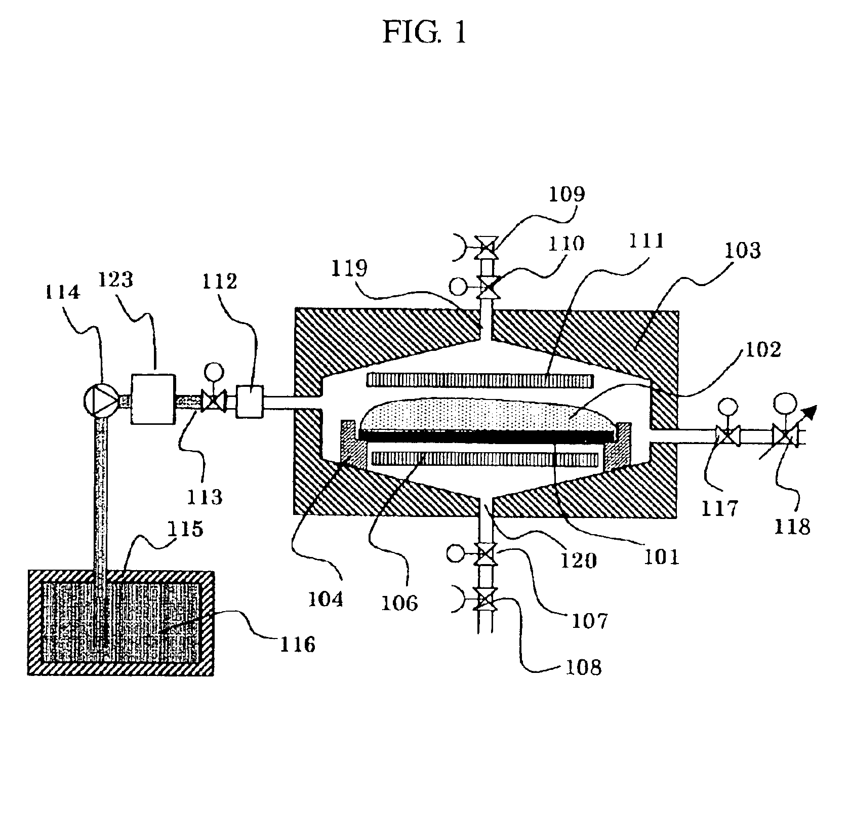
[0038]FIG. 1 is a sectional view showing an example of a microstructure drying treatment apparatus of the present invention. A high pressure vessel 103 that is a drying chamber of a substrate 101 has an upper lid portion and a lower vessel portion. The lid portion is opened and the substrate 101 is installed. The lid portion and the lower vessel portion use SUS 304 steel. The former portion is fixed and the latter portion is movable. Even either can be used. Further, the lid portion and the lower vessel portion have a passage into which a coolant that cools the inside of the vessel and a heating element. Moreover, the substrate 101 has a microstructure on the surface through development and rinsing processes after exposure. The surface is wholly coated with a rinsing liquid 102, and the substrate 101 is installed on a substrate holder 104 provided in the high pressure vessel 103. The high pressure vessel 103 is piped to a high pressure pump 114 and a liquid carbon dioxide vesse...

second embodiment

[0056

[0057]After processes (1) to (3) of the first embodiment, when the temperature of liquid carbon dioxide introduced at 5° C. in process (4) is controlled at about 28° C. by a heat element provided in the high pressure vessel 103, the specific gravity of the liquid carbon dioxide amounts to 0.70 g / ml and a specific gravity difference of the liquid carbon dioxide for the specific gravity of 0.80 g / ml of 2-propanol that is a rinsing liquid amounts to on the order of about 0.10. Accordingly, the 2-propanol can be collected at the bottom inside the high pressure vessel 103. Further, the substrate 101 can be heated uniformly by the top and bottom thermoregulators 106 and 111.

[0058]The 2-propanol collected at the bottom is selectively drained from the outlet 120 by performing operation in the same manner as process of (5) or later of the first embodiment. Subsequently, drying is terminated by decreasing the pressure up to atmospheric pressure via the same process as the first embodimen...

third embodiment

[0059

[0060]This embodiment can drain, substitute, and dry a rinsing liquid effectively in a short time by combining all processes in the first embodiment and all processes in the second embodiment even if two types of rinsing liquids are used at the same time. Further, this embodiment has also a fine pattern of less than 30 nm, and can dry a large-caliber substrate of 100 mm or more uniformly and in a short time without generating pattern collapse.

[0061]The present invention can provide a microstructure drying treatment method that can dry a substrate having a microstructure uniformly and in a short time of about several minutes without generating pattern collapse, and its apparatus and vessel.


PUM

PropertyMeasurementUnit
densityaaaaaaaaaa
widthaaaaaaaaaa
widthaaaaaaaaaa

Abstract

The object of the present invention is to provide a microstructure drying treatment method by which a substrate having a microstructure has a fine pattern of less than 30 nm and a large-caliber substrate of 100 mm or more can be dried uniformly and in a short time without generating pattern collapse, and its apparatus and its high pressure vessel. The present invention is a microstructure drying treatment method of introducing a fluid that is gas at normal temperature and pressure and is liquid under high pressure inside a high pressure vessel in which a substrate having a microstructure in a state immersed in or wet with a rinsing liquid in a liquid or supercritical state. The method forms a specific gravity difference between the rinsing liquid and fluid inside the high pressure vessel and collects the rinsing liquid to the upper side or lower side of the high pressure vessel by changing at least one side of the temperature and pressure of the fluid and changing the specific gravity of the fluid.

Description

FIELD OF THE INVENTION[0001]The present invention relates to a new microstructure drying treatment method and its apparatus, and its high pressure vessel.BACKGROUND OF THE INVENTION[0002]Conventionally, after a pattern is formed on a resist deposited on a silicon wafer via exposure, development, rinsing, and drying, a large-scale, high-density, and high-performance device is fabricated through processes of coating, etching, rinsing, and drying. In particular, a resist of a high molecular material is exposed by light, X rays, and an electron beam. In each process, because a fluid, such as a developer or a rinsing liquid, is used especially in a development or rinsing process, a drying process is necessary after a rinsing process.[0003]In this drying process, when the width of space between patterns formed on a resist substrate amounts to less than about 90 nm, Laplace force operates between the patterns by the surface tension (capillarity) of a fluid that is left between the patterns...

Claims


Application Information

Patent Timeline
Patent Type & Authority Patents(United States)
IPC IPC(8): H01L21/00F26B9/06F26B21/14G03F7/40H01L21/027H01L21/304
CPCG03F7/40H01L21/67034Y10S134/902
Inventor TAKTSU, HISAYUKIIWAYA, TORUMIYAZAWA, KOICHIKOUBORI, SAKAE
Owner HITACHI SCI SYST LTD
Why Eureka
Try Eureka