Microkeratome blades and methods of making

a microkeratome and blade technology, applied in the field of blades and blade drive combinations, can solve the problems of not foreclosed on the adoption of features in the holder which improve the cutting function, and achieve the effect of simplifying the manufacturing process, local nonuniformities, and reducing the introduction of stress points

Inactive Publication Date: 2005-08-02
WORTRICH THEODORE
View PDF14 Cites 17 Cited by
  • Summary
  • Abstract
  • Description
  • Claims
  • Application Information

AI Technical Summary

Benefits of technology

[0011]A cutting blade for microkeratomes in accordance with the invention is of conventional thinness, but configured with a geometry which minimizes the introduction of stress points and local nonu

Problems solved by technology

The form factor of the blade holder, for a particular microkeratome instrument, is essentially dictated by the desig

Method used


Image

  • Microkeratome blades and methods of making
  • Microkeratome blades and methods of making
  • Microkeratome blades and methods of making

Examples


Embodiment Construction

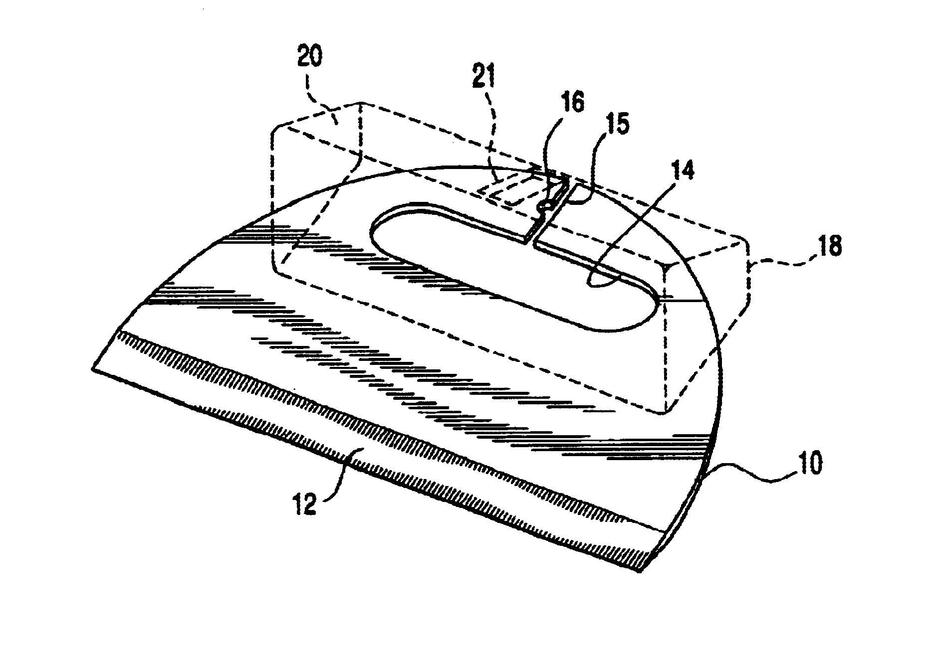
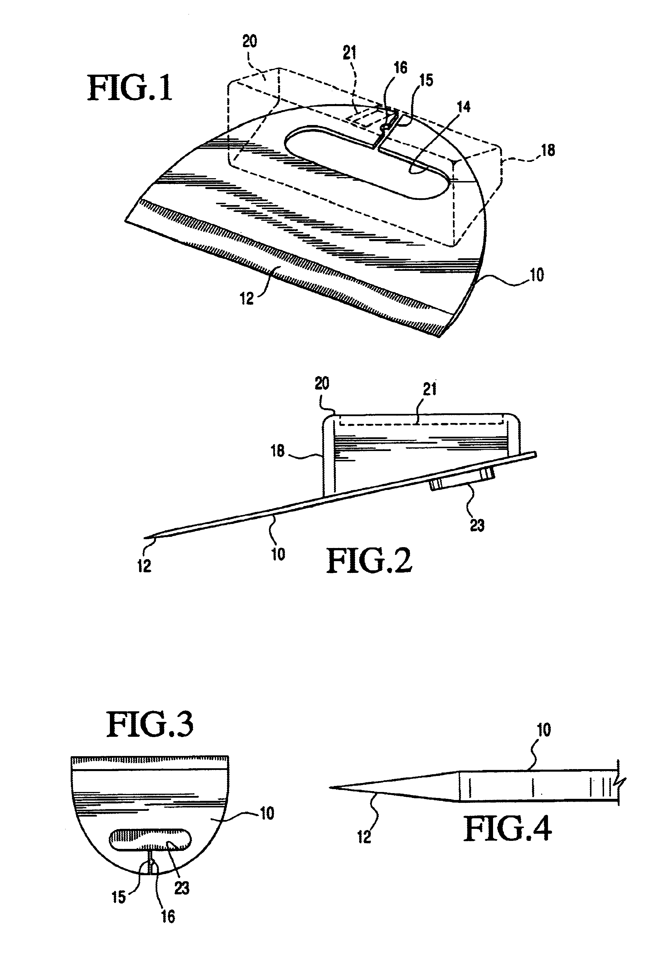
[0025]In the interest of brevity and simplicity, a detailed description is not provided herein of a microkeratome system with which the present invention may be used. Reference may be made to one of the above referenced patents for features of a typical microkeratome, bearing in mind that the Hellenkamp '009 patent on an arcuate path system is different in its drive mechanisms but still requires the precision and freedom from local nonuniformities and vibrating effects alluded to above. In FIGS. 1-3, the posterior boundary of a blade 10 is hemispherical in shape rearward of an anterior or leading cutting edge 12. The blade 10, which is of a surgical alloy, such as M-400 stainless steel, includes within its mid-region an ovoid aperture 14 that is open to the boundary through a small slot 15 in the blade 10 body. The slot 15 includes an indentation 16 which uniquely identifies the blade type. The holder 18, also called a driver, is a synthetic polymer element having a top surface 20 i...


PUM


Abstract

A blade and holder combination for use with a microkeratome, and including means for improving mechanical stability when the blade is reciprocated during cutting, as well as a peripheral configuration minimizing local nonuniformities. Blades in accordance with the invention have a generally hemispherical posterior geometry that include an adjacent centralized ovoid coupling aperture and a small centrally disposed access slot that may include indicia for denoting blade type. The hemispherical geometry minimizes both local deformities and the processing needed to assure that the product functions to provide a clean, uniform surgical result.

Description

[0001]This application claims benefit of application Ser. No. 60 / 272,021 filed on Feb. 28, 2001.BACKGROUND OF THE INVENTION[0002]This invention relates to blades and blade drive combinations for ophthalmic surgical procedures and more particularly to improved blades and blade holders for use in microkeratomes, and methods of making such blades.[0003]A very widely adopted modern technique for correction of deficiencies in human vision is based on a procedure which modifies the optics of the cornea. In this procedure, generally termed laser in-situ keratomileusis (LASIK), a flap is cut in the cornea. The flap is lifted and the exposed area is impacted by a laser beam in a precision pattern to ablate or vaporize small target areas on the cornea in accordance with the needed correction. The flap is immediately returned into its position, where it stays in place without the use of stitches or sutures.[0004]The instruments for making the cuts are called microkeratomes and comprise semiaut...

Claims


Application Information

Patent Timeline
IPC IPC(8): A61F9/013A61F9/007
CPCA61F9/0133
Inventor WORTRICH, THEODORE
Owner WORTRICH THEODORE
Why Eureka
Try Eureka