
Balloon catheter device

a balloon and catheter technology, applied in the field of balloon catheter devices, can solve the problems of affecting the operation of the catheter, and affecting the operation of the catheter

Inactive Publication Date: 2005-08-02
WL GORE & ASSOC INC
View PDF93 Cites 113 Cited by
  • Summary
  • Abstract
  • Description
  • Claims
  • Application Information

AI Technical Summary

Benefits of technology

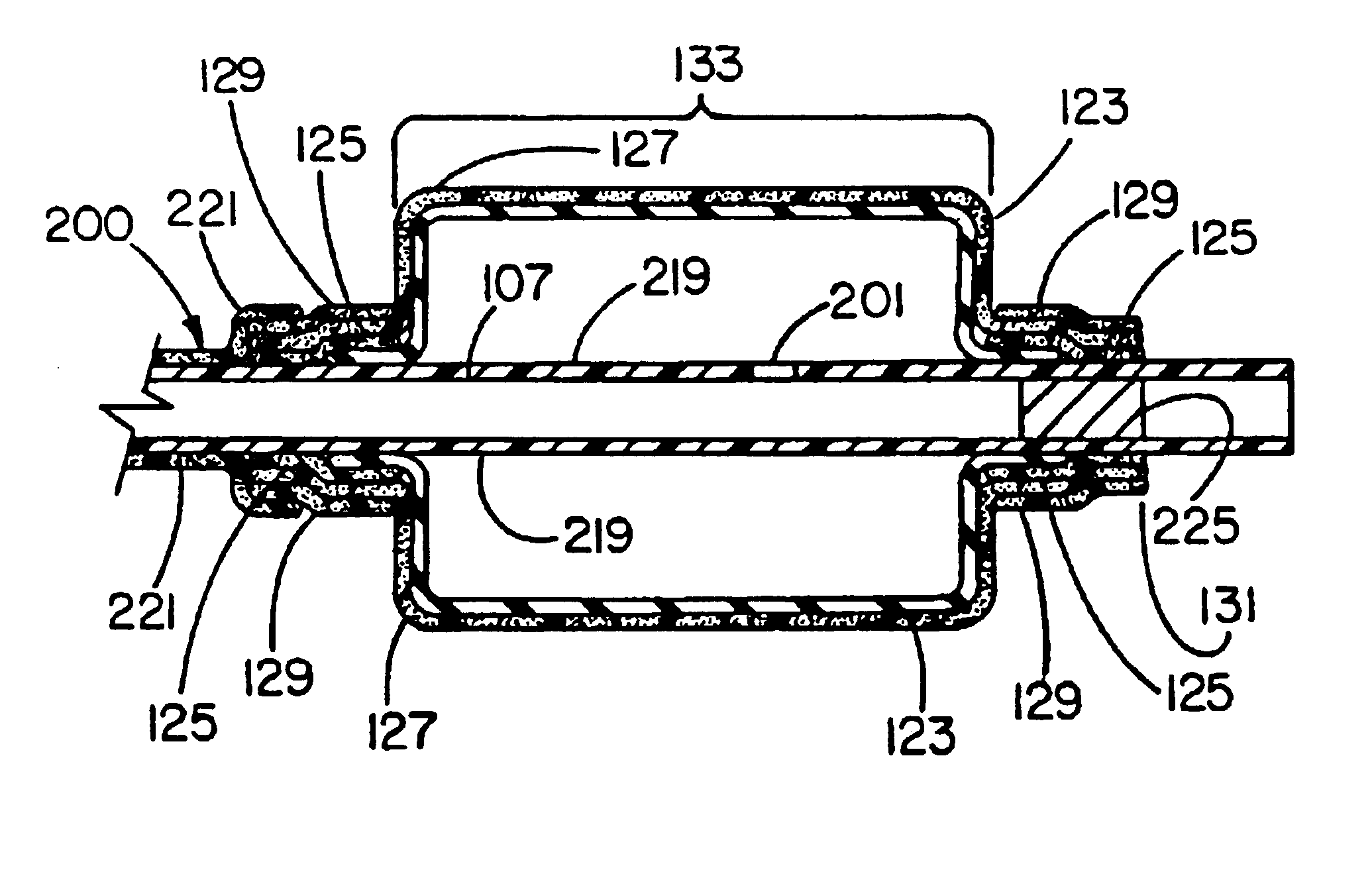
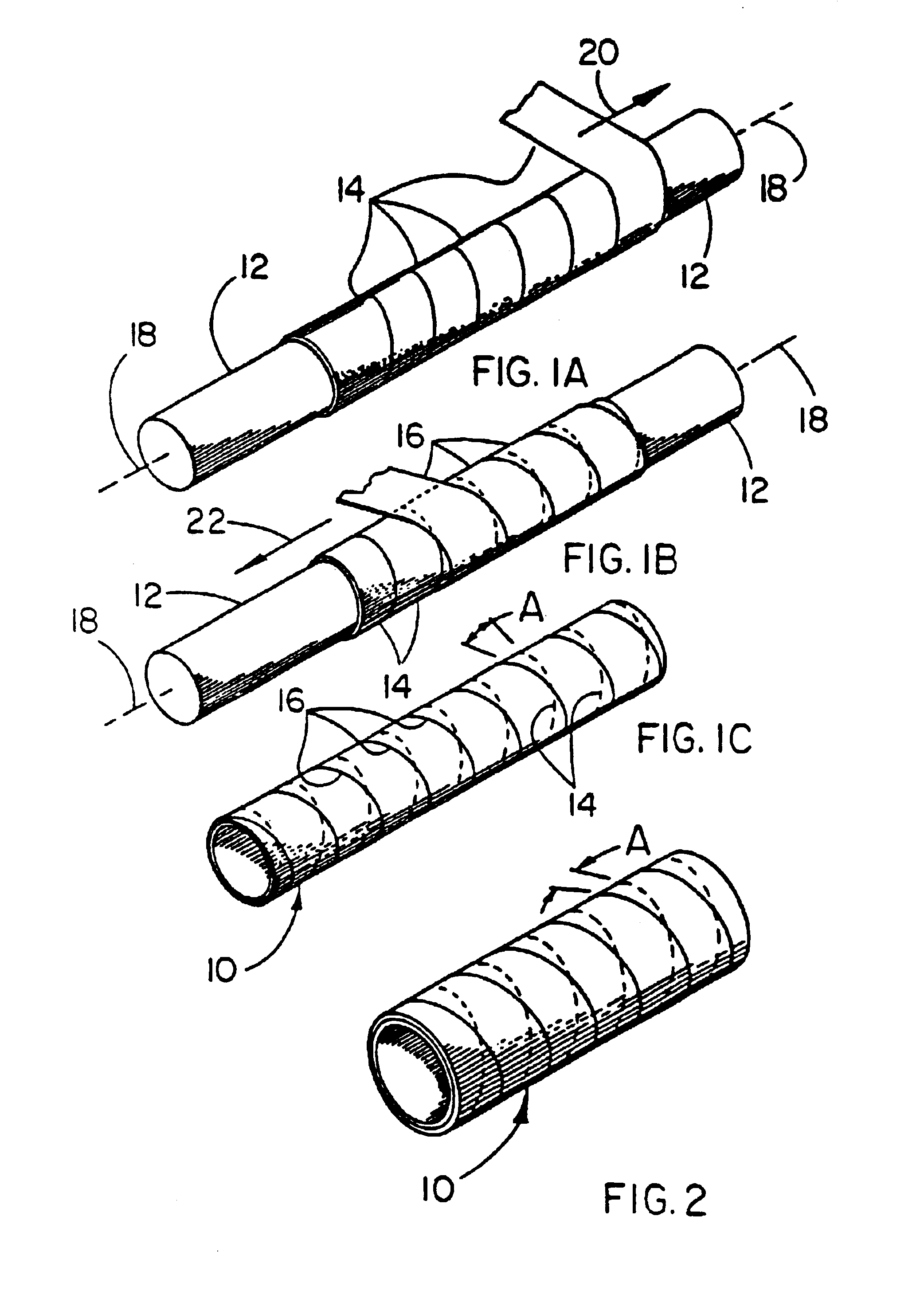
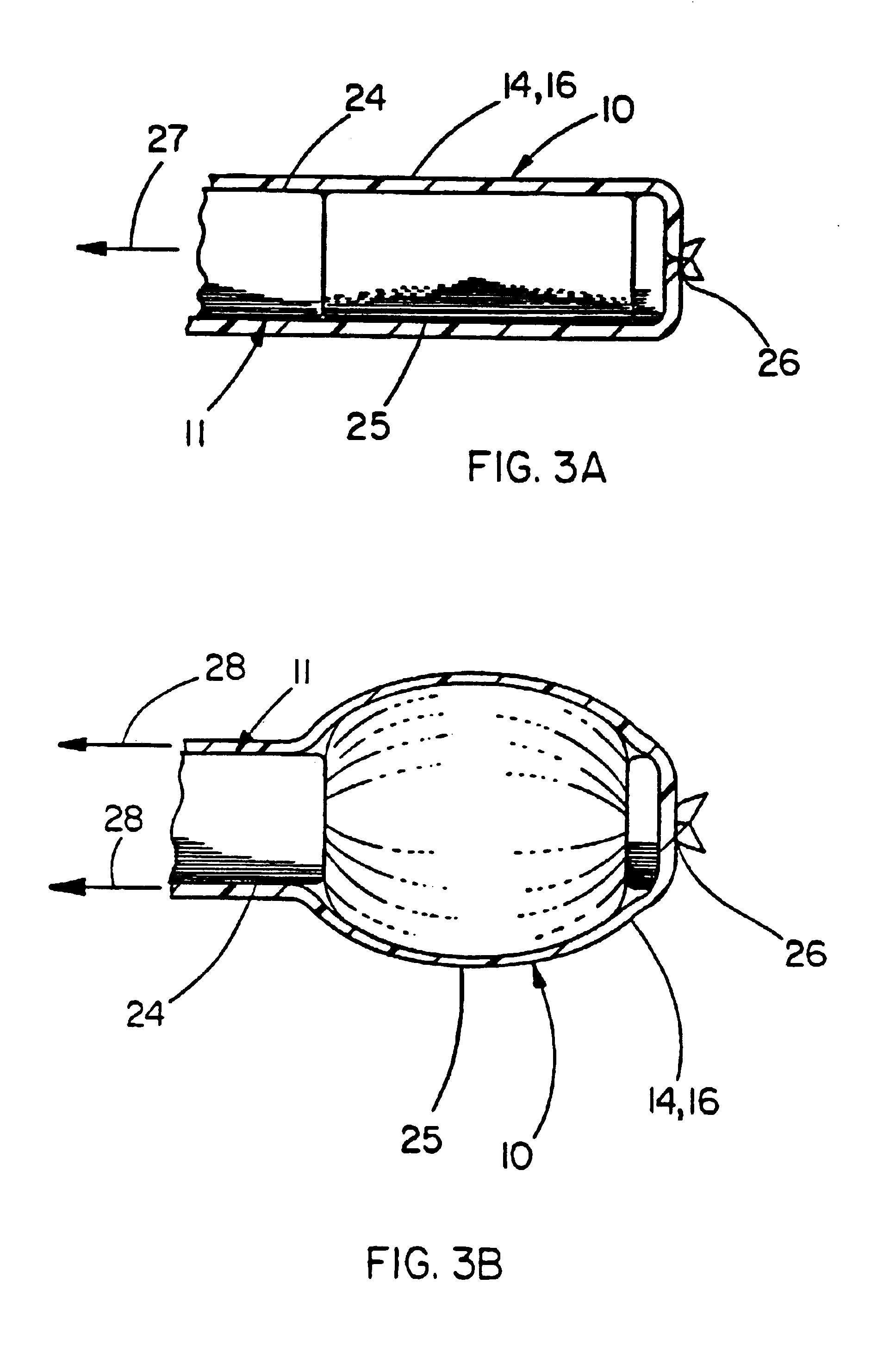
The present invention is an improved balloon catheter device for use in various surgical procedures. It has several technical effects. Firstly, the balloon has a burst strength equal to or greater than conventional PTA catheter balloons, but it can be withdrawn more easily due to its smooth and lubricious surface. Secondly, the balloon can be made in small sizes, which are currently not possible with conventional balloons. Thirdly, the balloon can smoothly deflate and recover to its pre-inflation size, unlike conventional PTA catheter balloons which have a flattened, irregular cross section after inflation. Fourthly, the balloon and balloon cover can be designed to inflate at lower pressures in one portion of the length than another, which makes it easier to control the inflation and deflation of the balloon. Fifthly, the balloon and balloon cover can be used as a cover for conventional PTA catheter balloons or latex embolectomy balloons, providing the covered balloon with the best features of both types of balloons. Lastly, the balloon catheter can distend a vessel or side branch without exerting significant force on the vessel or its branch, and it can also fllare the ends of prostheses to avoid unwanted constrictions.

Problems solved by technology

They tend to be self-limiting as to diameter in that they will normally distend up to the rated diameter and not distend appreciably beyond this diameter until rupture due to over-pressurization.
While the inelastic material of the balloon is generally effective in compacting deposits, it tends to collapse unevenly upon deflation, leaving a flattened, wrinkled bag, substantially larger in cross section than the balloon was when it was originally installed.
This enlarged, wrinkled bag may be difficult to remove, especially from small vessels.
Further, because these balloons are made from inelastic materials, their time to complete deflation is inherently slower than elastic balloons.
First, as has been noted, the strongest materials for balloon construction tend to be relatively inelastic.
The flattening of catheter balloons made from inelastic materials that occurs upon inflation and subsequent deflation makes extraction and navigation of a deflated catheter somewhat difficult.
Contrastly, highly elastic materials tend to have excellent recovery upon deflation, but are not particularly strong when inflated nor are they self-limiting to a maximum rated diameter regardless of increasing pressure.
This severely limits the amount of pressure that can be applied with these devices.
It is also somewhat difficult to control the inflated diameter of these devices.
A balloon that does not completely compact to its original size is prone to snag the device causing placement problems or even damage to the conduit or balloon.
Similarly, the use of a balloon that is constructed of tacky material will likewise cause snagging problems and possible displacement of the device.
Latex balloons are generally not used for device placement in that they are considered to have inadequate strength for such use.

Method used


Image

  • Balloon catheter device
  • Balloon catheter device
  • Balloon catheter device

Examples


example 1

[0044]This example illustrates the use of a balloon cover of the present invention over a commercially available angioplasty balloon. The balloon cover provides a means of returning the angioplasty balloon close to its original compact geometry after inflation and subsequent deflation, as well as providing the known chemical inertness and low coefficient of friction afforded by PTFE.

[0045]The balloon used was a MATCH 35® Percutaneous Transluminal Angioplasty (PTA) Catheter model number B508-412, manufactured by SCHNEIDER (Minneapolis, Minn.). This balloon when measured immediately after being removed from the protective sheath provided by the manufacturer had a minimum dimension of 2.04 mm and a maximum dimension of 2.42 mm. These measurements were taken from approximately the center of the balloon, as defined by the midpoint between the circumferentially-oriented radiopaque marker bands located at both ends of the balloon. A Lasermike model 183, manufactured by Lasermike, (Dayton, ...

example 2

[0051]This example illustrates the use of a balloon cover over a commercially available latex embolectomy balloon. The balloon cover provides a defined limit to the growth of the embolectomy balloon, a substantial increase in burst strength, and the known chemical inertness and low coefficient of friction afforded by PTFE.

[0052]The balloon used was a Fogarty® Thru-Lumen Embolectomy Catheter model 12TL0805F manufactured by Baxter Healthcare Corporation (Irvine, Calif.). This natural rubber latex balloon when measured immediately after being removed from the protective sheath provided by the manufacturer had a minimum dimension of 1.98 mm and a maximum dimension of 2.02 mm. These measurements were taken from approximately the center of the balloon, as defined by the midpoint between the radiopaque marker bands. A Lasermike model 183, manufactured by Lasermike, (Dayton, Ohio) was used to make the measurements while the balloon was rotated about its longitudinal axis. The shaft onto whi...

example 3

[0056]This example illustrates the use of a composite material in a balloon application. A balloon made from the composite material described below exhibits a predictable inflated diameter, high strength, exceptional compaction ratio and compaction efficiency ratio, as well as the known chemical inertness and low coefficient of friction afforded by PTFE.

[0057]A length of SILASTIC®Rx50 Silicone Tubing manufactured by Dow Corning Corporation (Midland, Mich.) having an inner diameter of 1.5 mm and an outer diameter of 2.0 mm was fitted coaxially over a 1.1 mm stainless steel mandrel and secured at both ends. The silicone tubing was coated with a thin layer of Translucent RTV 108 Silicone Rubber Adhesive Sealant manufactured by General Electric Company (Waterford, N.Y.). An 8 mm inner diameter film tube made in the same manner described in Example 1 was fitted coaxially over the stainless steel mandrel and the silicone tubing. Tension was manually applied to the ends of the film tube ca...


PUM

PropertyMeasurementUnit
pressureaaaaaaaaaa
pressuresaaaaaaaaaa
volumeaaaaaaaaaa

Abstract

Balloon catheters having the strength and maximum inflated diameter characteristics of an angioplasty balloon and having the recovery characteristics during deflation of an elastic embolectomy balloon. The balloon catheter can be made in very small sizes and has a lubricious and chemically inert outer surface. The balloon catheter is easy to navigate through tortuous passageways, is capable of rapid inflation and deflation and has high burst strengths. Balloon covers having these same characteristics are also described for use with conventional embolectomy balloons or angioplasty balloons.

Description

CROSS REFERENCE TO RELATED APPLICATIONS[0001]This application is a continuation of application Ser. No. 09 / 252,322, filed Feb. 18, 1999 now abandoned which is a continuation of application Ser. No. 08 / 858,309 filed May 19, 1997 now U.S. Pat. No. 6,120,477 which is a continuation-in-part of application Ser. No. 08 / 673,635 filed Jun. 26, 1996 now U.S. Pat. No. 5,868,704 which is a continuation-in-part of application Ser. No. 08 / 532,905 filed Sep. 18, 1995 now U.S. Pat. No. 5,752,934.FIELD OF THE INVENTION[0002]The present invention relates to catheter balloons used in a variety of surgical procedures and to balloon covers for use with catheter balloons.BACKGROUND OF THE INVENTION[0003]Balloon catheters of various forms are commonly employed in a number of surgical procedures. These devices comprise a thin catheter tube that can be guided through a body conduit of a patient such as a blood vessel and a distensible balloon located at the distal end of the catheter tube. Actuation of the...

Claims


Application Information

Patent Timeline
Patent Type & Authority Patents(United States)
IPC IPC(8): A61L29/00A61L29/14A61M25/10A61L29/08A61L29/12A61M25/00A61F2/06A61L29/04
CPCA61F2/958A61L29/041A61L29/085A61L29/12A61L29/146A61M25/0014A61M25/10A61M25/1029A61M25/1034C08L27/18C08L83/04C08L75/04C08L27/12Y10T428/1359A61M2025/1075A61M2025/1081A61F2250/0039Y10T428/1334
Inventor CAMPBELL, CAREY V.LAGUNA, ALVARO J.SPENCER, MARK S.
Owner WL GORE & ASSOC INC
Learn More