Optical recording method performing power control with variable linear velocity

a technology of linear velocity and power control, applied in the field of optical recording methods and recording apparatuses of recordable optical disks, can solve problems such as unstable pit formation and failure to write, and achieve the effects of stab detection, high quality level, and stable detection

Inactive Publication Date: 2005-08-02
YAMAHA CORP
View PDF6 Cites 15 Cited by
  • Summary
  • Abstract
  • Description
  • Claims
  • Application Information

AI Technical Summary

Benefits of technology

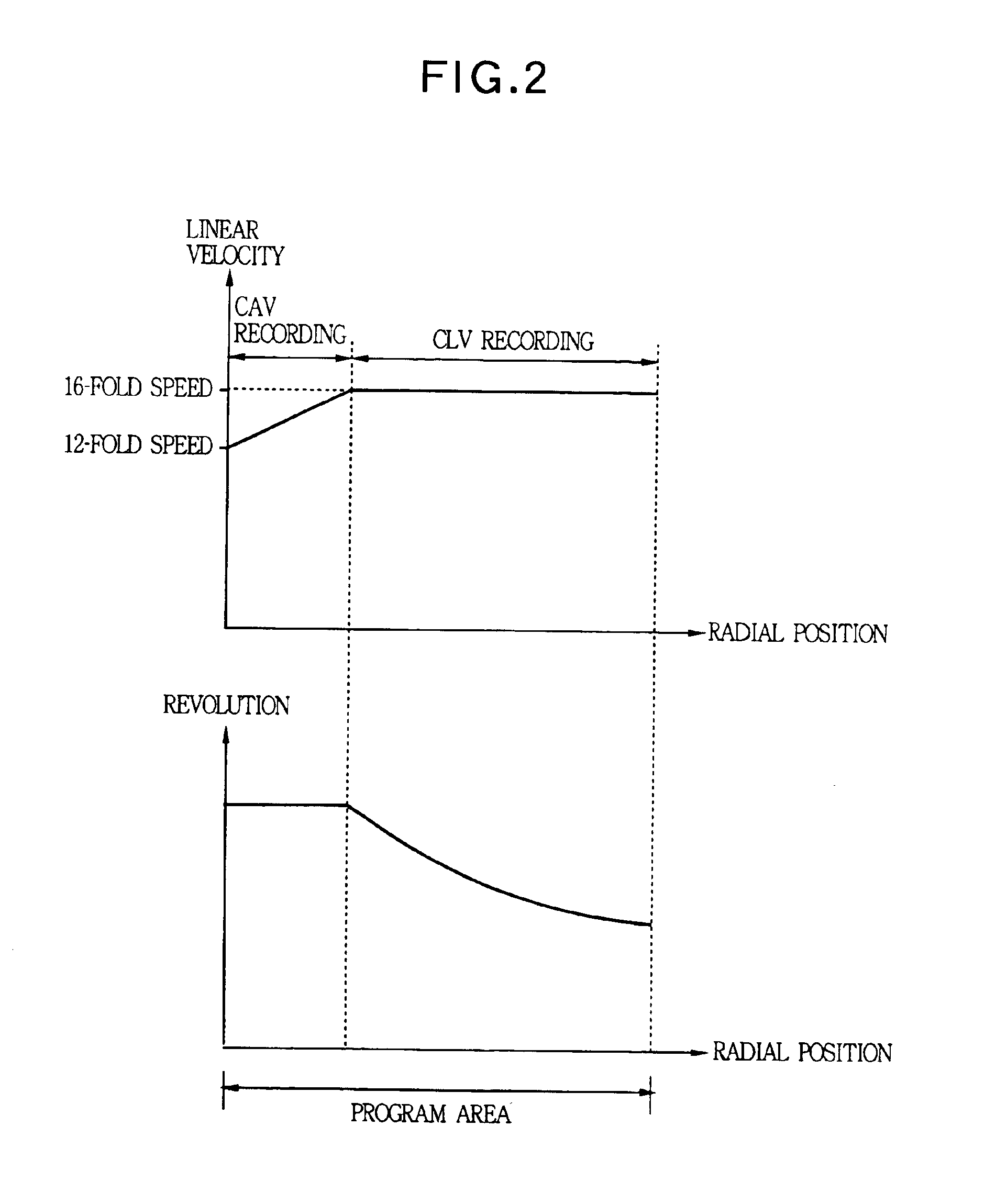
[0016]According to the present invention, there is provided an optical disk recording method for performing recording of data with a variable linear velocity multiplication factor in accordance with a radial position of an irradiation optical beam on an optical disk, the method comprising carrying out a test recording before starting an actual recording at a plurality of test linear velocity multiplication factors lower than a variable range of an actual linear velocity multiplication factor used in the actual recording so as to obtain an appropriate writing power of the irradiation optical beam for each of the test linear velocity multiplication factors, setting a characteristic of an appropriate writing power in function of the radial position of the irradiation optical beam for the actual linear velocity multiplication factor based on the appropriate writing powers obtained for each of the test linear velocity multiplication factors, and carrying out the actual recording such that an appropriate writing power of the irradiation optical beam is calculated based on the set characteristic for the actual linear velocity multiplication factor in accordance with the radial position of the irradiation optical beam. According to the present invention, since the test recording is carried out with each of a plurality of linear velocity multiplication factors lower than a variable range of the linear velocity multiplication factor used in the actual recording, even if the linear velocity multiplication factor used in the actual recording is high, the test recording can be performed with a relatively low number of rotations. Further, self-excited vibration during the test recording can be suppressed, and an appropriate writing power can be stably detected, thereby effecting the actual recording at a high quality level.
[0017]According to the present invention, there is provided an optical disk recording method for performing recording of data at a variable linear velocity multiplication factor in accordance with a radial position of an irradiation optical beam on an optical disk, the method comprising carrying out a test recording before starting an actual recording at a first linear velocity multiplication factor within a variable range of an actual linear velocity multiplication factor used in the actual recording and at a second linear velocity multiplication factor below the variable range of the actual linear velocity multiplication factor so as to obtain an appropriate writing power of the irradiation optical beam for each of the first and second linear velocity multiplication factors, setting a characteristic of an appropriate writing power in function of the radial position of the irradiation optical beam for the actual linear velocity multiplication factor based on the appropriate writing powers obtained for each of the first and second linear velocity multiplication factors, and carrying out the actual recording such that an appropriate writing power of the irradiation optical beam is calculated based on the set characteristic for the actual linear velocity multiplication factor in accordance with the radial position of the irradiation optical beam. According to the present invention, since the test recording is carried out with one linear velocity multiplication factor within a variable range used in the actual recording and one or a plurality of linear velocity multiplication factors lower than that variable range, the test recording can be performed with a relatively low number of rotations in at least one point. Furthermore, self-excited vibration during the test recording can be suppressed and an appropriate writing power can be stably detected, thereby effecting the actual recording at a high quality level. Moreover, since the test recording is carried out with a linear velocity multiplication factor within a variable range used in the actual recording and a linear velocity multiplication factor lower than that variable range, the test recording can be performed with the linear velocity multiplication factors different from each other, thereby setting a characteristic having less errors of, e.g., an inclination.

Problems solved by technology

Therefore, in recording on the inner peripheral side of the disk, the self-excited vibration of a drive mechanism becomes large (in case of a disk having the mass eccentricity in particular), and the pit formation becomes unstable.
Data transfer is too late for reproduction on the inner peripheral side, and so-called buffer under-run occurs, which may lead to a failure of writing.

Method used


Image

  • Optical recording method performing power control with variable linear velocity
  • Optical recording method performing power control with variable linear velocity
  • Optical recording method performing power control with variable linear velocity

Examples


example 1

When Using a Super Cyanine Type CD-R Disk Manufactured by A (Which Will be Referred to as a “Disk A” hereinafter)

[0087]FIG. 10 shows a characteristic of a value β of a reproduction RF signal relative to the writing power when performing recording while changing the writing power in various linear velocity multiplication factors by using the disk A in many ways. FIG. 11 shows a characteristic of a C1 error relative to the value β when EFM-demodulating the reproduction RF signal. FIG. 12 shows a characteristic of the pit jitter relative to the value β of the reproduction RF signal. FIG. 13 is shows a characteristic of the writing power relative to the writing linear velocity multiplication factor for each value β calculated by developing the characteristic illustrated in FIG. 10. According to FIG. 13, the characteristic of the writing power relative to the linear velocity multiplication factor when maintaining the value β to a predetermined value and effecting recording can be approxi...

example 2

When Using a Cyanine Type CD-R Disk Manufactured by B (Which Will be Referred to as a “Disk B” hereinafter)

[0095]FIG. 19 shows a characteristic of a value β of a reproduction RF signal relative to a writing power when performing recording by using the disk B while changing the writing power in various linear velocity multiplication factors in many ways. FIG. 20 shows a characteristic of a C1 error relative to the value β when EFM-demodulating the reproduction RF signal. FIG. 21 shows a characteristic of the pit jitter relative to the value β of the reproduction RF signal. FIG. 22 shows a characteristic of the writing power relative to the writing linear velocity multiplication factor for each value β obtained by developing the characteristic illustrated in FIG. 19. According to FIG. 22, the characteristic of the writing power relative to the linear velocity multiplication factor when maintaining the value β to a predetermined value to effect recording can be approximated by the foll...

example 3

When Using a Phthalocyanine Type CD-R Disk Manufactured by C (Which Will be Referred to as a “Disk C” hereinafter)

[0104]FIG. 26 shows a characteristic of a value β of a reproduction RF signal relative to a writing power when recording is carried out by using a disk C while changing the writing power in various linear multiplication factors in many ways. FIG. 27 shows a characteristic of a C1 error relative to the value β when EFM-demodulating the reproduction RF signal. FIG. 28 shows a characteristic of the pit jitter relative to the value β of the reproduction RF signal. FIG. 29 shows a characteristic of a writing power relative to a writing linear velocity multiplication factor for each value β calculated by developing the characteristic illustrated in FIG. 26. According to FIG. 29, the characteristic of the writing power relative to the linear velocity multiplication factor when maintaining the value β to a predetermined value to effect recording can be approximated by the follow...


PUM

PropertyMeasurementUnit
diameteraaaaaaaaaa
wavelengthsaaaaaaaaaa
wavelengthaaaaaaaaaa

Abstract

An optical disk recording method performs recording of data at a variable linear velocity multiplication factor in accordance with a radial position of a irradiation optical beam on an optical disk. The method is carried out by the steps of performing an actual recording with a variable writing power y=ax+b of the irradiation optical beam in accordance with a linear velocity multiplication factor x where the constant a is determined to a fixed value according to a type of the optical disk, performing a test recording before starting the actual recording such that the test recording is carried out with a test linear velocity multiplication factor to obtain an appropriate writing power of the irradiation optical beam, and setting the constant b by solving the function y=ax+b with using the results of the test recording, whereby the actual recording can be performed with an appropriate writing power y calculated based on the function y=ax+b having the set constants a and b.

Description

BACKGROUND OF THE INVENTION[0001]The present invention relates to a recording method and recording apparatus of a recordable optical disk such as a CD-R (CD recordable) disk, a DVD-R (DVD recordable) disk and others for controlling a correction quantity of a recording strategy concerning an irradiation time of an optical beam to an appropriate value, and for controlling an optical beam to an appropriate writing power to enable recording with a high quality level in case of recording with a variable linear velocity multiplication factor in accordance with a radial position of the optical beam 0n an optical disk in the radial direction.[0002]As a recording method of a constant linear velocity (CLV) recording type optical disk such as CD-R or a DVD-R, high-speed recording for recording at a linear velocity higher than a standard linear velocity (nominal reference speed) may be adopted.[0003]In constant linear velocity recording, a number of rotations of a spindle motor increases as a r...

Claims


Application Information

Patent Timeline
Patent Type & Authority Patents(United States)
IPC IPC(8): G11B7/125G11B7/0045G11B7/00G11B7/126G11B7/1267
CPCG11B7/0045G11B7/126G11B7/1267
Inventor NAKAJO, YUKIHISA
Owner YAMAHA CORP
Why Eureka
Try Eureka