Hydrocephalus valve

a technology of hydrocephalus and valve body, which is applied in the direction of wound drains, intravenous devices, medical devices, etc., to achieve the effect of improving the adaptation of fluid drainage, reliably and simply constructed

Inactive Publication Date: 2005-08-09
MIETHKE CHRISTOPH
View PDF41 Cites 150 Cited by
  • Summary
  • Abstract
  • Description
  • Claims
  • Application Information

AI Technical Summary

Benefits of technology

[0037]It is particularly advantageous if the switching valve is stable in the open position and in the closed position when the electrical actuating system is not activated, as energy is only needed to switch over the switching valve, but not to maintain one of the two end positions of the switching valve.
[0038]In a preferred embodiment, it is provided that the switching valve has a spherical valve body, which rests in a sealing manner in the closed position on a valve aperture and in the open position rests in a recess laterally adjacent to the valve aperture. This produces a particularly simple construction for a switching valve of this type.

Problems solved by technology

In the case of people suffering from hydrocephalus there is the problem that raised internal pressure of the brain occurring because of excessive cerebrospinal fluid leads to serious problems for the people affected.
The brain tissue is therefore damaged and permanently weakened and there are various symptoms such as dizziness, walking difficulty, headaches, nausea, sickness and dementia.
Untreated, the disease can ultimately lead to the death of the patient.
In the standing position, such valves lead systematically to unphysiologically low, negative pressure in the head of the patient, which can lead to serious complications.
Nevertheless, these valves do not eliminate the difficulty, either, that the physical conditions in the drainage system of the patient change as a function of posture.
If the valves are adjusted to a low opening pressure, this will, on the one hand, favour the clinical outcome, but, on the other hand, simultaneously dramatically increase the danger of over-drainage in the standing position.
Conversely, although adjustment to a very high value can reduce the danger of overdrainage, the clinical outcome to be achieved is thus simultaneously lastingly impaired, as the now available opening pressure for the lying position is significantly too high.
However, opposing this advantage is the serious drawback that the subcutaneous pressure around the valve housing has a considerable influence on the mode of operation of the valve.
Owing to tissue growth or an unfavourable position of the patient, this pressure may vary by considerable values and therefore even lead to absolute valve closure.
In comparison to conventional valves, these valves have not proved superior, either (Drake, Toronto).
Flow-regulating systems specifically have the following problems.1. It is technically impossible to ensure the value for the allowed drainage rate.
Particles in the liquor such as, for example cellular constituents have a dramatic influence on function and can easily clog the valve.
International comparative studies have shown that this principle was not able to improve the treatment outcomes of hydrocephalus (Drake et al).
Although many problems could be solved by valve systems of this type the following aspects also remain unsolved here:1. Adaptation of the valve characteristics to growth or age-related changes or other changes of physiological boundary conditions is not possible.2. A deliberate, non-invasive adjustment of the valve properties with different adjustments for different body positions of the patient is not possible.3. Consistent treatment of patients right up to the drainage (which has perhaps become superfluous) being turned off, is not possible.4. The appropriate adaptation of liquor drainage to individual particularities is not possible.5. Valves remain a narrow point of discharge.
Such signals cannot be taken into consideration in previously offered solutions.7. Intelligent control, which evaluates as a function of the situation, of valve properties is impossible with previous solutions.8. Subsequent analysis of incidents is not possible.
However, the detection of pressure values in the patient is connected with great uncertainties, and therefore this method is not suitable for satisfactorily controlling the fluid drainage in the long term.
This necessitates an extraordinarily complicated construction of the valve, and moreover it must be assumed that the controlled variables, i.e. flow and pressure are constant over time and only have to be adjusted if necessary in the course of doctors' visits to then be valid for a longer time period.

Method used


Image

  • Hydrocephalus valve
  • Hydrocephalus valve
  • Hydrocephalus valve

Examples


Embodiment Construction

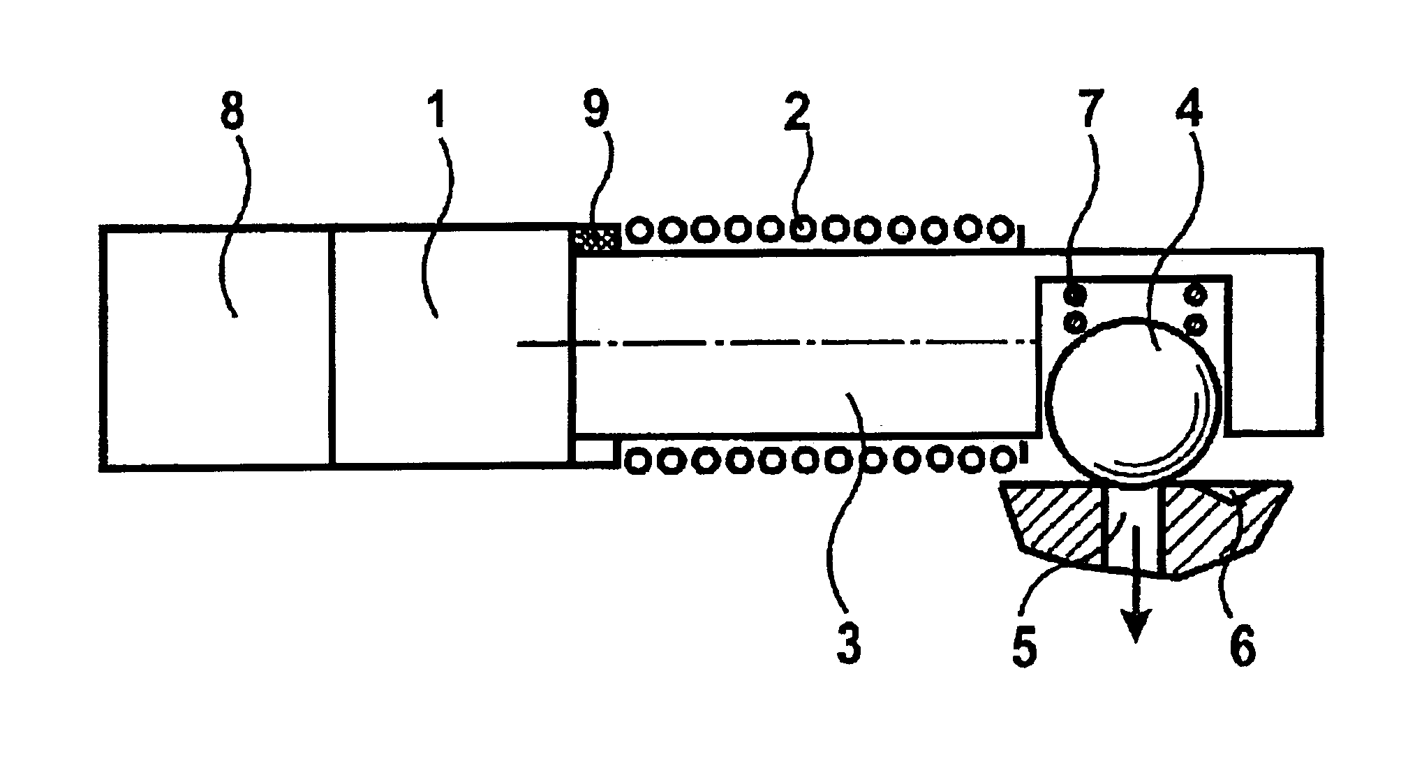
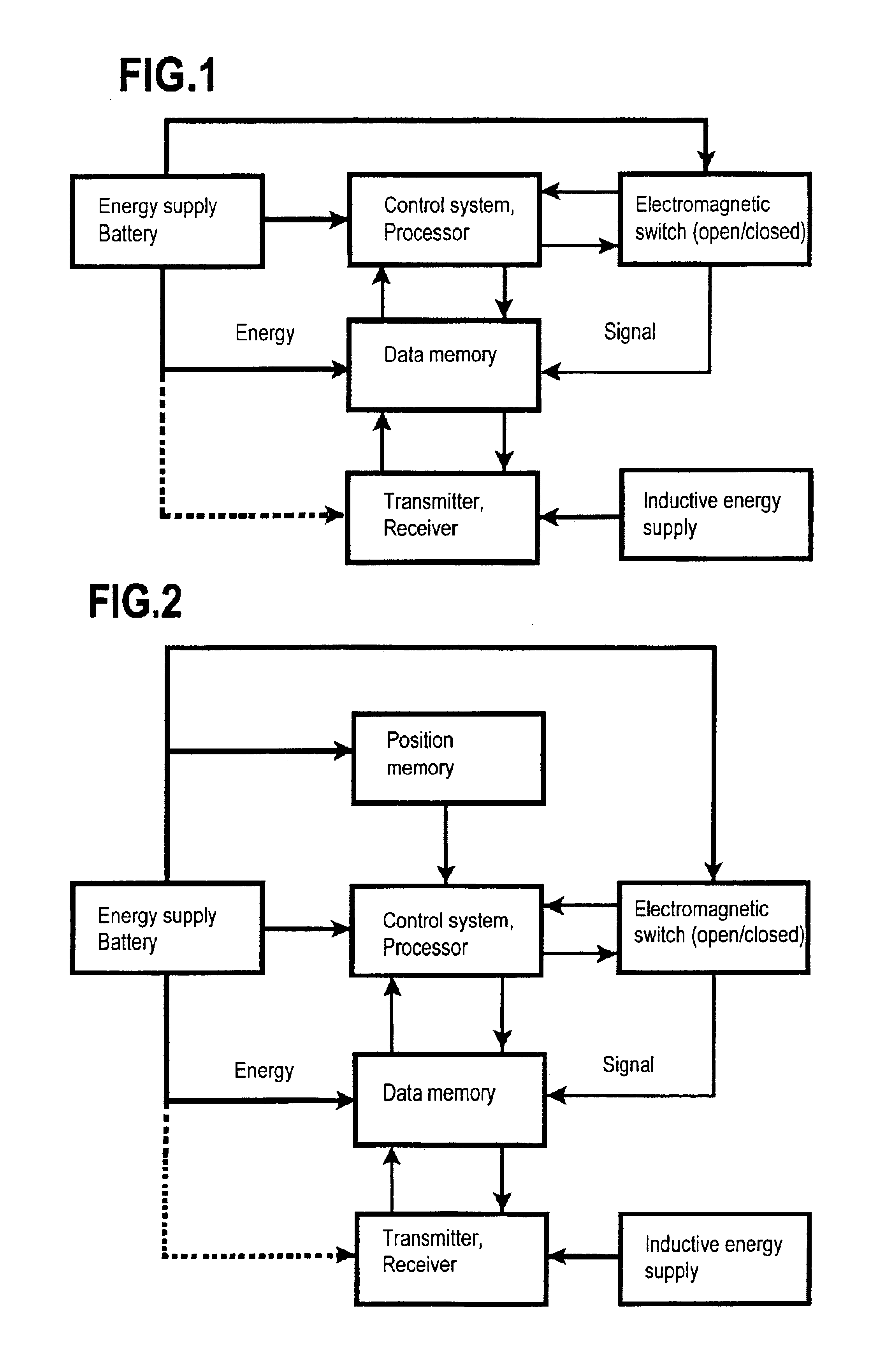
[0048]The hydrocephalus valve system shown in the drawings comprises an energy unit (battery), a processor, a data memory, an electromagnetic switch, a transmitting and receiving unit and optionally a unit for inductive energy supply. FIG. 1 shows the block diagram for the mode of operation of the invention.

[0049]FIG. 1 shows the simplest mode of construction of a valve system. A time-dependent control signal s(t) is input into the data memory via the transmitter. The control signal s(t) contains control information which can be individually set up for each patient about the opening state of the electromagnetic switch at each point in time t. Thus, for example, the opening state at night can last longer than during the day. There is the possibility of setting up an individual profile according to the habits or needs of the patient. This opening profile can be adapted at any time to possible changes.

[0050]The data memory passes the information to the control unit which in turn contro...


PUM


Abstract

In order to allow improved adaptation to the situation existing in a patient in the case of a hydrocephalus valve with an electric actuating system comprising a control system opening and closing the hydrocephalus valve, it is proposed that the control system is a time control system.

Description

[0001]This application is a continuation of international application No. PCT / EP01 / 14585 filed on Dec. 11, 2001.[0002]The present disclosure relates to the subject matter disclosed in international application PCT / EP 01 / 14585 of Dec. 11, 2001, which is incorporated herein by reference in its entirety and for all purposes.BACKGROUND OF THE INVENTION[0003]The invention relates to a hydrocephalus valve with an electrical actuating system, comprising a control system opening and closing the hydrocephalus valve.[0004]In the case of people suffering from hydrocephalus there is the problem that raised internal pressure of the brain occurring because of excessive cerebrospinal fluid leads to serious problems for the people affected. The brain tissue is therefore damaged and permanently weakened and there are various symptoms such as dizziness, walking difficulty, headaches, nausea, sickness and dementia. Untreated, the disease can ultimately lead to the death of the patient. The type and ex...

Claims


Application Information

Patent Timeline
Patent Type & Authority Patents(United States)
IPC IPC(8): A61M27/00A61M1/00
CPCA61M27/006A61M2205/3337
Inventor MIETHKE, CHRISTOPH
Owner MIETHKE CHRISTOPH
Why Eureka
Try Eureka