Apparatus for and method of frequency conversion

a technology of apparatus and frequency, applied in the field of online optics, can solve the problems of not being able to laser, requiring too large current densities, and not being suitable for continuous wave operation

Inactive Publication Date: 2005-08-09
PBC LASERS LTD
View PDF7 Cites 18 Cited by
  • Summary
  • Abstract
  • Description
  • Claims
  • Application Information

AI Technical Summary

Benefits of technology

[0082]Unless otherwise defined, all technical and scientific terms used herein have the same meaning as commonly understood by one of ordinary skill in the art to which this invention belongs. Although methods and materials similar or equivalent to those described herein can be used in t

Problems solved by technology

Thus, it is of key importance to ensure very low losses at each reflection, otherwise, lasing will either not be possible, or will require too large current densities, not suitable for continuous wave operation.
The disadvantage of the edge-emitting laser over the VCSEL is astigmatism phenomenon often occurring when circular output aperture are employed.
Additionally, as opposed to the VCSEL, in the edge-emitting laser a temperature increase results in a significant wavelength shift caused by the bandgap narrowing of semiconductors with increasing temperature.
An additional disadvantage of the semiconductors lasers is a poor beam quality, wide spectrum and poor temperature stability of the wavelength.
However, the above techniques suffer from the following inefficiency limitation.
Thus, the inefficiency of the process is originated in the step of converting the diode laser (or lamp) light to the solid-state laser light.
However, the conversion efficiency of these techniques is still rather low.
It is recognized that the low conversion efficiency requires the use of high power diode lasers, which inevitably have to be cooled.
Thus, the inefficiency problem is aggravated by the energy loss due to heating which is at least 90% of the total energy.
Another disadvantage is the fact that the solid-sta

Method used


Image

  • Apparatus for and method of frequency conversion
  • Apparatus for and method of frequency conversion
  • Apparatus for and method of frequency conversion

Examples


Embodiment Construction

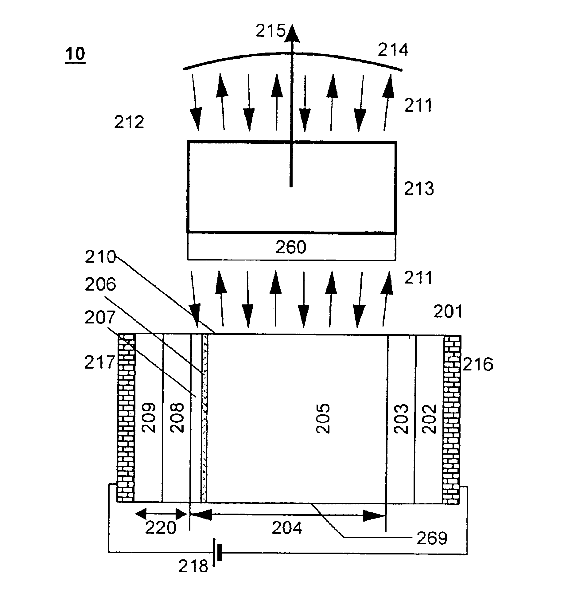
[0096]The present invention is of an apparatus for and method of frequency conversion which can be used for converting a laser frequency. Specifically, the present invention can be used for providing a laser light having a frequency in a wide spectral range. More specifically, the present invention can be used in, e.g., optical storage applications, where short wavelength is needed to increase the density of the stored information by reducing the characteristic feature size, or in projection displays, where green and blue lasers are needed for full-color applications. The present invention is further of a method of manufacturing the apparatus.

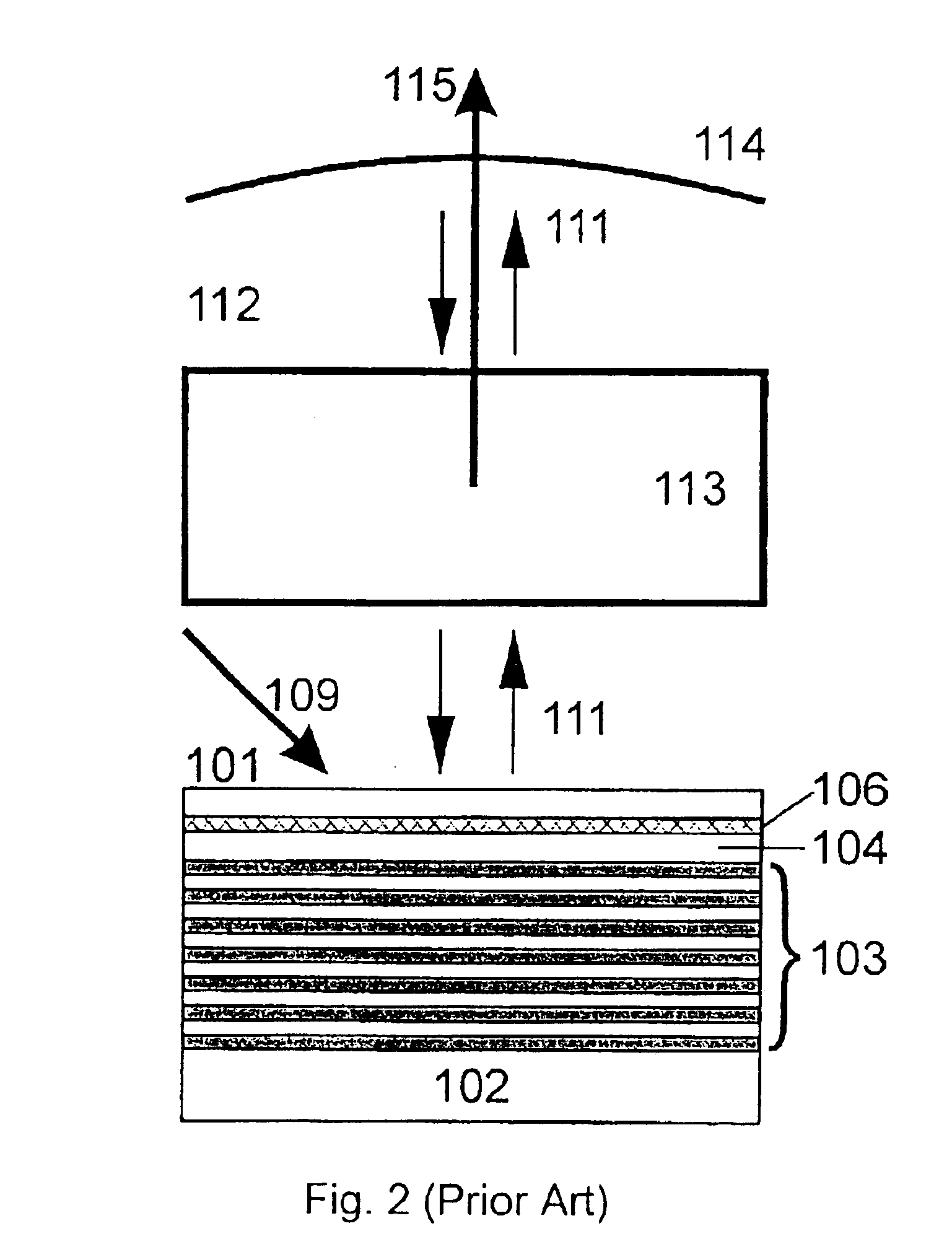
[0097]For purposes of better understanding the present invention, as illustrated in FIGS. 3-8 of the drawings, reference is first made to the construction and operation of a conventional (i.e., prior art) frequency conversion apparatus as illustrated in FIG. 2.

[0098]FIG. 2 illustrates a prior art frequency conversion apparatus, which is based o...


PUM


Abstract

Apparatus for frequency conversion of light, the apparatus comprises: a light-emitting device for emitting a light having a first frequency, the light-emitting device being an edge-emitting semiconductor light-emitting diode having an extended waveguide selected such that a fundamental transverse mode of the extended waveguide is characterized by a low beam divergence. The apparatus further comprises a light-reflector, constructed and designed so that the light passes a plurality of times through an external cavity, defined between the light-emitting device and the light-reflector, and provides a feedback for generating a laser light having the first frequency. The apparatus further comprises a non-linear optical crystal positioned in the external cavity and selected so that when the laser light having the first frequency passes a plurality of times through the non-linear optical crystal, the first frequency is converted to a second frequency being different from the first frequency.

Description

[0001]This is a continuation in part of PCT / IL02 / 00718, filed Aug. 29, 2002 which claims the benefit of priority from U.S. patent application Ser. No. 09 / 946,016, filed Sep. 4, 2001, the contents of which are hereby incorporated by reference.FIELD AND BACKGROUND OF THE INVENTION[0002]The present invention relates to non-linear optics and, more particularly, to an apparatus for frequency conversion of light based on a diode laser structure.[0003]Semiconductor lasers play an important role in optical fiber transmission systems, signal amplification systems, wavelength division multiplexing transmission systems, wavelength division switching systems, wavelength cross-connection systems and the like. In addition semiconductor lasers are useful in the field of optical measurements.[0004]A semiconductor laser (first proposed in 1959) is based on current injection of non-equilibrium carriers into a semiconductor active medium, resulting in population inversion and sufficient modal gain to ...

Claims


Application Information

Patent Timeline
IPC IPC(8): H01S5/10H01S5/00H01S5/183
CPCB82Y10/00B82Y20/00H01S5/18341H01S5/1021H01S5/105H01S5/1833H01S5/2027H01S5/3211H01S2301/166H01S5/11
Inventor LEDENTSOV, NIKOLAISHCHUKIN, VITALY
Owner PBC LASERS LTD
Why Eureka
Try Eureka