
Exhaust gas aftertreatment systems

a technology of exhaust gas aftertreatment and exhaust gas, which is applied in electrical control, machine/engine, separation process, etc., can solve the problems of not all ammonia may be utilized in the scr catalyst, affect the nox conversion efficiency of the system, and may therefore be emitted into the atmosphere, so as to improve speed up the warm-up of the scr catalyst. , the effect of improving the nox conversion efficiency

Inactive Publication Date: 2005-08-16
FORD GLOBAL TECH LLC
View PDF40 Cites 227 Cited by
  • Summary
  • Abstract
  • Description
  • Claims
  • Application Information

AI Technical Summary

Benefits of technology

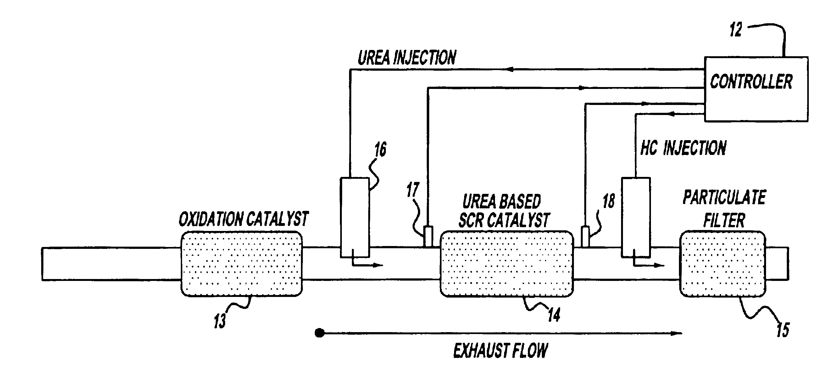
[0009]An advantage of the present invention is that improved NOx conversion efficiency is achieved by placing the SCR catalyst higher upstream than the prior art systems, due to faster SCR catalyst warm-up and its higher operating temperatures.
[0010]Another advantage of the present invention is that placing the particulate filter farthest downstream eliminates the risk of the thermal damage to other emission system components during filter regeneration.
[0011]Yet another advantage of the present invention is that ammonia that slipped from the SCR catalyst is oxidized in the particulate filter, thus resulting in reduced tailpipe ammonia emissions.

Problems solved by technology

Vehicles equipped with diesel or another lean burn engine offer the benefit of increased fuel economy, however, control of NOx emissions in such systems is complicated due to the high content of oxygen in the exhaust gas.
Namely, because the SCR catalyst is located farthest downstream of the engine in this configuration, there is a significant delay in achieving light-off temperatures thus negatively affecting the system's NOx conversion efficiency.
Still another disadvantage of the prior art system is that not all ammonia may be utilized in the SCR catalyst, and may therefore be emitted into the atmosphere.

Method used


Image

  • Exhaust gas aftertreatment systems
  • Exhaust gas aftertreatment systems
  • Exhaust gas aftertreatment systems

Examples


Embodiment Construction

)

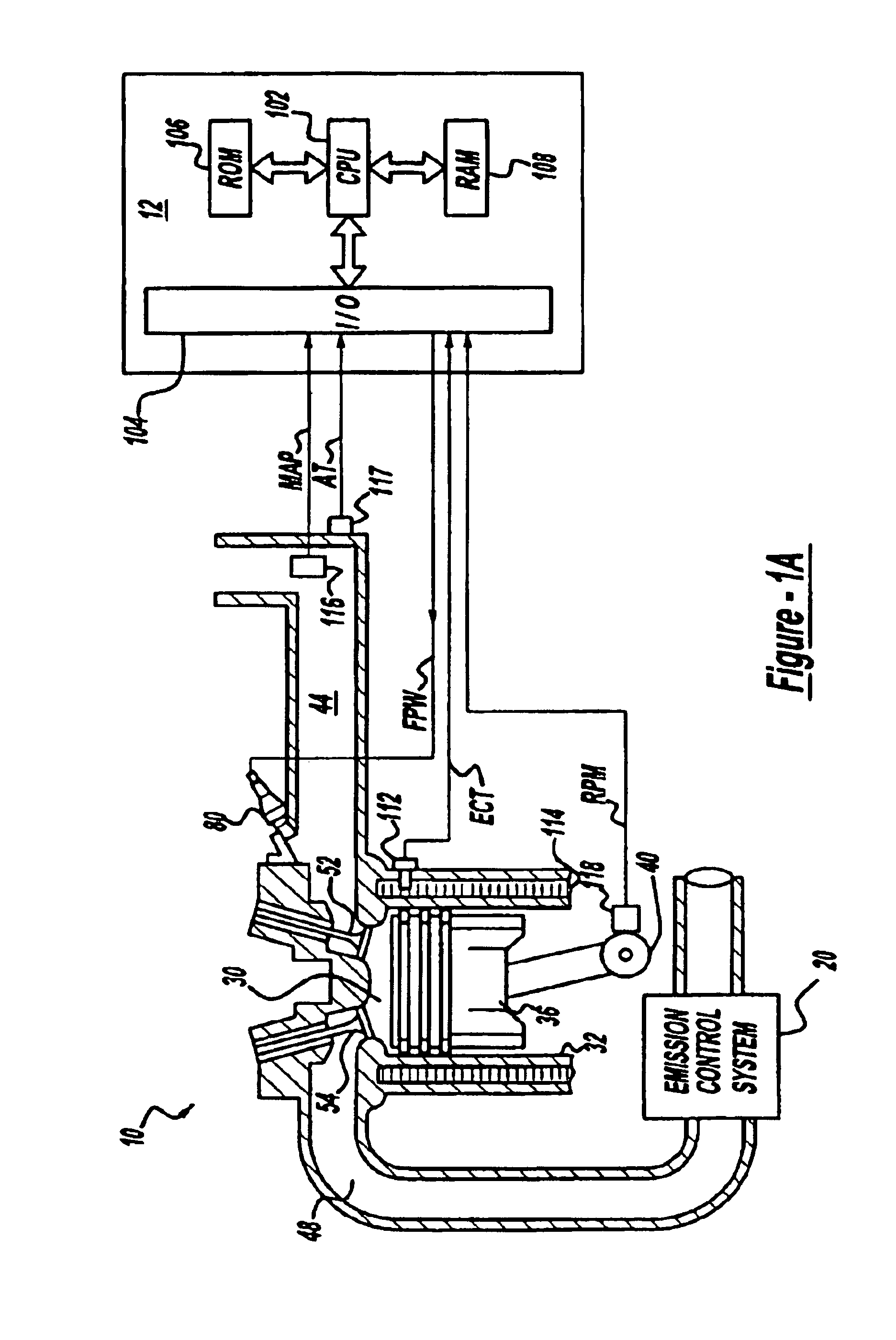
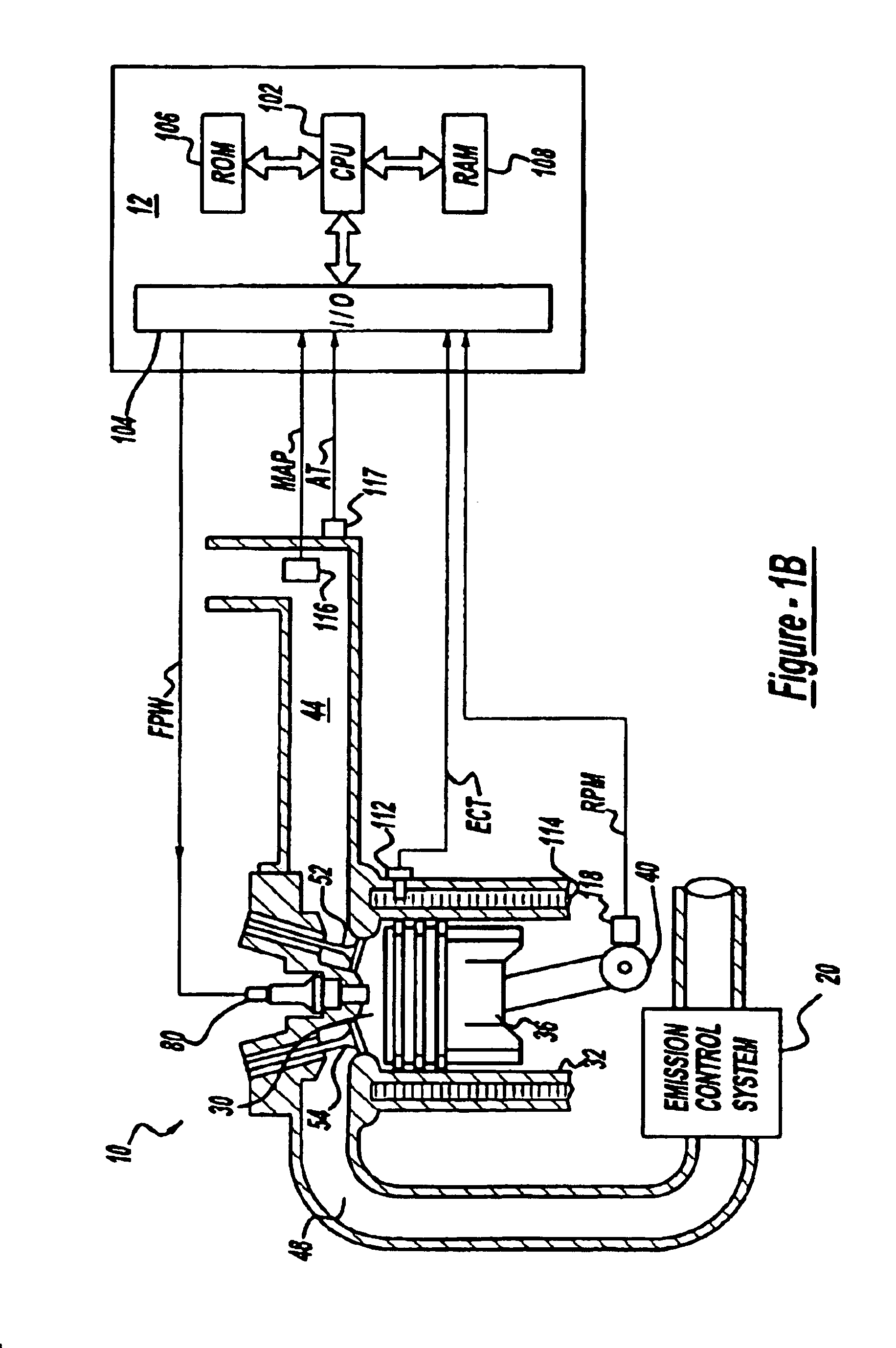
[0021]Internal combustion engine 10, comprising a plurality of cylinders, one cylinder of which is shown in FIG. 1A, is controlled by electronic engine controller 12. Engine 10 includes combustion chamber 30 and cylinder walls 32 with piston 36 positioned therein and connected to crankshaft 40. Combustion chamber 30 is shown communicating with intake manifold 44 and exhaust manifold 48 via respective intake valve52 and exhaust valve 54. Intake manifold 44 is also shown having fuel injector 80 coupled thereto for delivering liquid fuel in proportion to the pulse width of signal FPW from controller 12. Both fuel quantity, controlled by signal FPW and injection timing are adjustable. Fuel is delivered to fuel injector 80 by a fuel system (not shown), including a fuel tank, fuel pump, and fuel rail (not shown).

[0022]Controller 12 is shown in FIG. 1A as a conventional microcomputer including: microprocessor unit 102, input / output ports 104, read-only memory 106, random access memory 108...


PUM


Abstract

A system for effective NOx and particulate matter control in a diesel or other lean burn internal combustion engine is presented. The system includes a urea-based SCR catalyst having an oxidation catalyst coupled upstream of it and a particulate filter coupled downstream of the SCR catalyst. This system configuration results in improved NOx conversion due to fast SCR catalyst warm-up and higher operating temperatures. Additionally, placing the particulate filter last in this system configuration reduces tailpipe ammonia emissions as well as prevents any thermal damage to the SCR catalyst due to the particulate filter regeneration.

Description

FIELD OF INVENTION[0001]The present invention relates to an emission control system for diesel and other lean-burn vehicles and, more specifically, to a new system configuration designed achieve improved emission control.BACKGROUND AND SUMMARY OF THE INVENTION[0002]Current emission control regulations necessitate the use of catalysts in the exhaust systems of automotive vehicles in order to convert carbon monoxide (CO), hydrocarbons (HC), and nitrogen oxides (NOx) produced during engine operation into unregulated exhaust gasses. Vehicles equipped with diesel or another lean burn engine offer the benefit of increased fuel economy, however, control of NOx emissions in such systems is complicated due to the high content of oxygen in the exhaust gas. In this regard, Selective Catalytic Reduction (SCR) catalysts, in which NOx is continuously removed through active injection of a reductant, such as urea, into the exhaust gas mixture entering the catalyst, are know to achieve high NOx conv...

Claims


Application Information

Patent Timeline
IPC IPC(8): B01D53/94F01N3/023F01N3/025F01N3/20F01N3/035F01N7/02F01N7/00F02D41/14F01N13/02
CPCB01D53/9431B01D53/9495F01N3/023F01N3/0253F01N3/035F01N3/2066F01N13/0093F01N13/009F01N2240/16F01N2570/12F01N2570/14F01N2610/02F01N2610/03F01N2610/08F01N2610/10F02D41/1475Y02T10/24Y02A50/20Y02T10/12
Inventor TENNISON, PAUL JOSEPHLAING, PAUL M.LAMBERT, CHRISTINE KAYHAMMERLE, ROBERT HENRYRUONA, WILLIAM CHARLES
Owner FORD GLOBAL TECH LLC
Learn More