Apparatus and method for diagnosis and therapy of electrophysiological disease

a technology of electrophysiology and apparatus, applied in the field of electrophysiological disease diagnosis and treatment, can solve the problems of high morbidity and mortality, difficult to perform by even the most skilled surgeons, and high thrombosis, and achieves the effects of reducing the risk of thrombosis, easy visualization, and fast us

Inactive Publication Date: 2005-08-16
ST JUDE MEDICAL ATRIAL FIBRILLATION DIV
View PDF18 Cites 75 Cited by
  • Summary
  • Abstract
  • Description
  • Claims
  • Application Information

AI Technical Summary

Benefits of technology

[0008]The present invention meets these and other objectives by providing epicardial ablation devices and methods useful for creating transmural lesions that electrically isolate the pulmonary veins for the treatment of atrial fibrillation. The devices and methods may be utilized through a small access port in the chest, preferably through a subxiphoid penetration, and positioned within the pericardium and around the pulmonary veins. Advantageously, the devices and methods do not require the large thoracic incision used in the conventional maze procedure, and may be used on the beating heart without cardiopulmonary bypass. By eliminating the need for ablation within the left atrium, the risk of thrombus formation is minimized. The devices and methods of the invention are more easily visualized, faster to use, and more accurately positionable than known cardiac ablation catheters and devices, enable the formation of continuous, uninterrupted lesions around the pulmonary veins, and protect extracardiac tissues from injury.
[0009]In a first embodiment, a method of forming a transmural lesion in a wall of the heart adjacent to the pulmonary veins comprises the steps of placing at least one ablation device through a thoracic incision and through a pericardial penetration so that the at least one ablation device is disposed in contact with an epicardial surface of the heart wall; positioning the at least one ablation device adjacent to the pulmonary veins on a posterior aspect of the heart while leaving the pericardial reflections intact; and transmurally ablating the heart wall with the at least one ablating device to create at least one transmural lesion adjacent to the pulmonary veins. The ablation device is preferably placed through a small puncture, incision, or access port in the chest, either between the ribs or in a subxiphoid position, for minimal trauma, with visualization provided by fluoroscopy, endoscopy, transesophageal echocardiography, or other conventional form of minimally-invasive imaging. While the method may be performed with the heart stopped and circulation supported with cardiopulmonary bypass, the method is preferably performed with the heart beating so as to minimize morbidity, mortality, complexity and cost.
[0012]In addition, a mechanism may be provided for urging all or part of the working end against the epicardium to ensure adequate contact with the ablation devices. This mechanism may be, for example, one or more suction holes in the working end through which suction may be applied to draw the working end against the epicardium, or an inflatable balloon mounted to the outer side of the working end such that, upon inflation, the balloon engages the inner wall of the pericardium and forces the working end against the epicardium. This also functions to protect extracardiac tissues such as the pericardium from injury by retracting such tissues away from the epicardial region which is being ablated, and, in the case of the balloon, providing an insulated barrier between the electrodes of the ablation probe and the extracardiac tissues.
[0013]The apparatus may be either a single integrated device or two or more devices which work in tandem. In either case, the apparatus may have two or more tips at the working end which are positioned on opposing sides of a tissue layer such as a pericardial reflection. A device may be provided for approximating the two free ends on opposing sides of the tissue layer, such as an electromagnet mounted to one or both of the free ends. In this way, a continuous lesion may be created in the myocardium from one side of the pericardial reflection to the other without puncturing or cutting away the pericardial reflection.

Problems solved by technology

While very effective in treating atrial fibrillation, the maze procedure is highly invasive, high in moribidity and mortality, and difficult to perform by even the most skilled surgeons.
This location creates significant difficulties for endocardial ablation devices for several reasons.
Second, the elongated and flexible endovascular ablation devices are difficult to manipulate into the complex geometries required for forming the pulmonary venous lesions and to maintain in such positions against the wall of the beating heart.
This is very time-consuming and can result in lesions which do not completely encircle the pulmonary veins or which contain gaps and discontinuities.
Third, visualization of endocardial anatomy and endovascular devices is often inadequate and knowing the precise position of such devices in the heart can be difficult, resulting in misplaced lesions.
However, on the left side of the heart where the pulmonary venous lesions are formed, thrombus can be carried by the bloodstream into the coronary arteries or the vessels of the head and neck, potentially resulting in myocardial infarction, stroke or other neurologic sequelae.
Finally, the heat generated by endocardial devices which flows outward through the myocardium cannot be precisely controlled and can damage extracardiac tissues such as the pericardium, the phrenic nerve and other structures.
If, on the other hand, epicardial ablation devices are utilized to form the pulmonary venous lesions, other challenges are presented.
First, the posterior location of the pulmonary veins is extremely difficult to access through thoracic incisions without gross manipulations of the heart.
Such manipulations are not generally possible if minimally-invasive techniques are being utilized via small thoracic access ports, or if the procedure is being performed on a beating heart without cardiopulmonary bypass.
Such cutting or puncturing of the pericardial reflections is risky and difficult, particularly if working through small incisions in the chest without a clear view and open access to the posterior side of the heart.
Furthermore, surgical repair of any damaged tissue is almost impossible without highly invasive open heart surgery.

Method used


Image

  • Apparatus and method for diagnosis and therapy of electrophysiological disease
  • Apparatus and method for diagnosis and therapy of electrophysiological disease
  • Apparatus and method for diagnosis and therapy of electrophysiological disease

Examples


Embodiment Construction

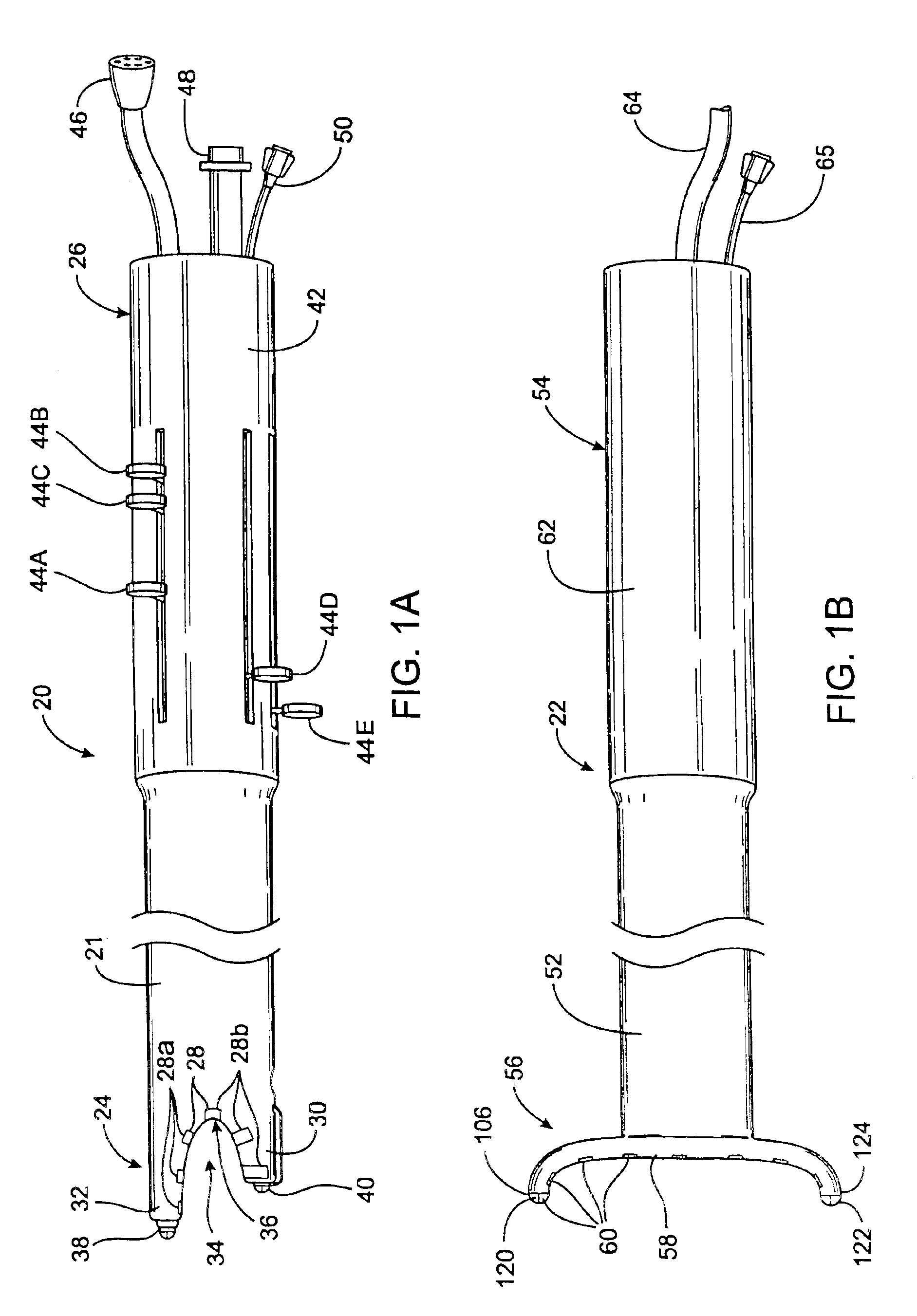
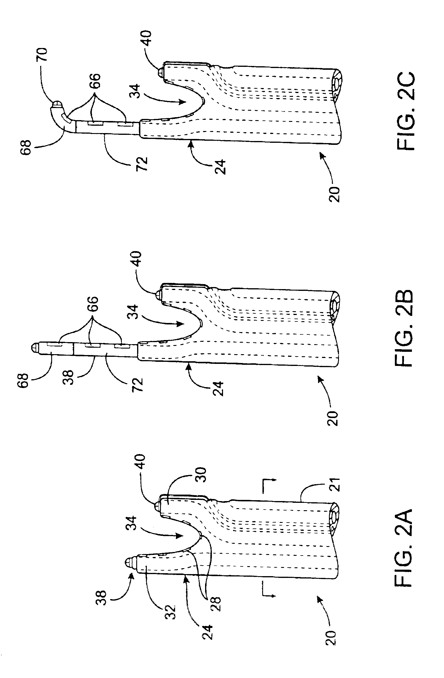
[0072]FIGS. 1A-1B illustrate a first embodiment of the apparatus of the invention. In this embodiment, the apparatus comprises a left ablation probe 20, shown in FIG. 1A, and a right ablation probe 22, shown in FIG. 1B, which work in tandem to form a transmural lesion isolating the pulmonary veins from the surrounding myocardium. Left ablation probe 20 has a flexible shaft 21 extending to a working end 24 configured for insertion into the chest cavity through a small incision, puncture or access port. Opposite working end 24, shaft 21 is attached to a control end 26 used for manipulating the working end 24 from outside the chest. Shaft 21 is dimensioned to allow introduction through a small incision in the chest, preferably in a subxiphoid location, and advanced to the pulmonary veins on the posterior side of the heart. Preferably, shaft 21 is configured to be flexible about a first transverse axis to allow anterior-posterior bending and torsional flexibility, but relatively stiff a...


PUM


Abstract

The invention provides apparatus and methods for mapping conduction pathways and creating lesions in the heart wall for the treatment of atrial fibrillation. The apparatus may include at least one epicardial ablation probe having a plurality of electrodes for creating a lesion. The apparatus and method facilitate the formation of a lesion which electrically isolates the pulmonary veins from the surrounding myocardium.

Description

CROSS-REFERENCE TO RELATED APPLICATIONS[0001]This application is a continuation of Ser. No. 09 / 440,825 filed Nov. 15, 1999, now U.S. Pat. No. 6,474,340, which is a continuation of Ser. No. 09 / 356,476 filed Jul. 19, 1999, now U.S. Pat. No. 6,311,692, which is a continuation in part of Ser. No. 09 / 157,824 filed Sep. 21, 1998, now U.S. Pat. No. 6,237,605.FIELD OF THE INVENTION[0002]This invention relates generally to the diagnosis and treatment of electrophysiological diseases of the heart, and more specifically to devices and methods for epicardial mapping and ablation for the treatment of atrial fibrillation.BACKGROUND OF THE INVENTION[0003]Atrial fibrillation results from disorganized electrical activity in the heart muscle, or myocardium. The surgical maze procedure has been developed for treating atrial fibrillation and involves the creation of a series of surgical incisions through the atrial myocardium in a preselected pattern so as to create conductive corridors of viable tissu...

Claims


Application Information

Patent Timeline
Patent Type & Authority Patents(United States)
IPC IPC(8): A61B18/02A61B18/14A61B18/00A61N1/06A61N7/02A61N7/00A61B17/34A61B5/0408A61B5/042A61B17/00A61N1/362
CPCA61B18/00A61B18/02A61B18/1402A61B18/1482A61B18/1492A61N1/06A61N7/02A61B5/0422A61B18/148A61B19/5244A61B2017/00247A61B2017/003A61B2017/3419A61B2018/00023A61B2018/0016A61B2018/00232A61B2018/00261A61B2018/00285A61B2018/00291A61B2018/00351A61B2018/00363A61B2018/00392A61B2018/00577A61B2018/00654A61B2018/00797A61B2018/00839A61B2018/142A61B2018/145A61B2018/1467A61B2018/1472A61B2019/5217A61B2019/5278A61B2218/002A61B2218/007A61N1/362A61B34/20A61B2090/3614A61B2090/3782A61N1/3629A61B5/287
Inventor VASKA, MATTHIASPLESS, BANJAMINGALLUP, DAVID A.ULSTAD, JR., JACK E.ANDERSON, SCOTT C.RICHMAN, ROXANNE L.
Owner ST JUDE MEDICAL ATRIAL FIBRILLATION DIV
Why Eureka
Try Eureka