Male fertility assay method and device

a technology for assaying male fertility and assaying methods, applied in the field of assaying male fertility, can solve the problems of limiting the analysis of semen samples for couples who are failing to conceive, men are particularly unwilling to seek semen analysis, and women are reluctant to seek medical advi

Inactive Publication Date: 2005-08-16
QN DIAGNOSTICS LLC
View PDF20 Cites 33 Cited by
  • Summary
  • Abstract
  • Description
  • Claims
  • Application Information

AI Technical Summary

Benefits of technology

[0008]In this embodiment, the sperm in the sample may be labeled with a fluorescent reporter, and step (1) may include measuring fluorescence emission in the collection reservoir. This labeling may include exposing sperm to a fluorescence reporter having a cleavable ester group that promotes uptake of the reporter into sperm in an uncharged state, and inhibits efflux of the reporter from sperm in a charged, cleaved-ester state.

Problems solved by technology

Analysis of semen samples for couples who are failing to conceive is currently limited by several factors.
Many couples are reluctant to seek medical advice for fertility problems until difficulties and stressors have persisted for long periods of time.
Once medical advice is sought, men are particularly unwilling to seek semen analysis due to embarrassment and lack of privacy.
The need for trained personnel and laboratory testing is partly responsible for the high cost of fertility management.
Low cost and private alternatives to semen analysis, such as the in-home cell count assay available from the UK, fail to discriminate between sperm cells in the semen sample and other cell types and fail to analyze any motility characteristics of the sperm cells within the sample.

Method used


Image

  • Male fertility assay method and device
  • Male fertility assay method and device
  • Male fertility assay method and device

Examples


first embodiment

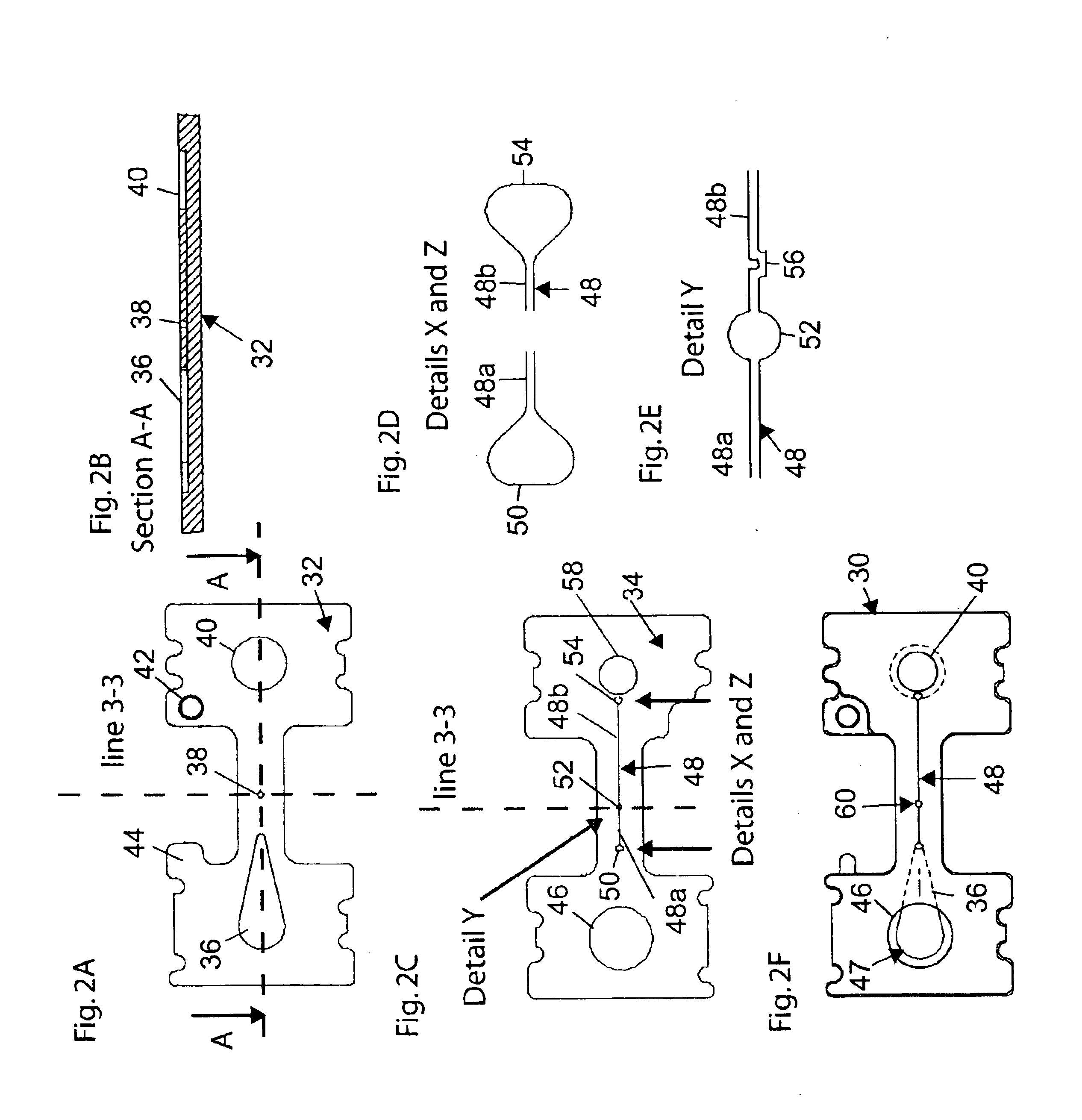
[0050]This section describes components of a collection reservoir device constructed in accordance with the invention. With reference to FIGS. 2A-2F, there is shown at FIG. 2F, a microfluidics structure 30 formed of a bottom plate 32 (FIG. 2A) bonded to an aligned top plate 34 (FIG. 2C) As seen best in FIGS. 2A and 2B, bottom plate 32 includes a tear-drop shaped recess 36 formed in its upper surface, at the upstream end region of the plate, a central cylindrical reservoir recess 38, which will form part of a collection reservoir in the structure, and a downstream recess 40. Also formed in the lower plate is a circular alignment recess 42 used in aligning the lower and upper plates when the two are bonded together, and a tab 44 used in aligning an optical element on structure 30, as will be seen.

[0051]Considering now the construction of top plate 34, and with reference to FIGS. 2C-2E, a sample-receiving opening 46 is formed at the upstream end of the plate. A microfluidics channel 48...

second embodiment

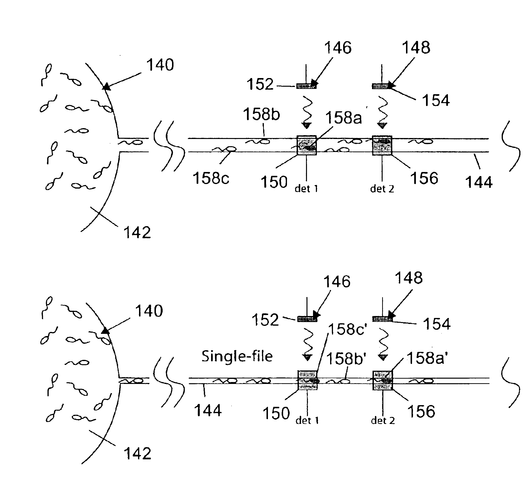
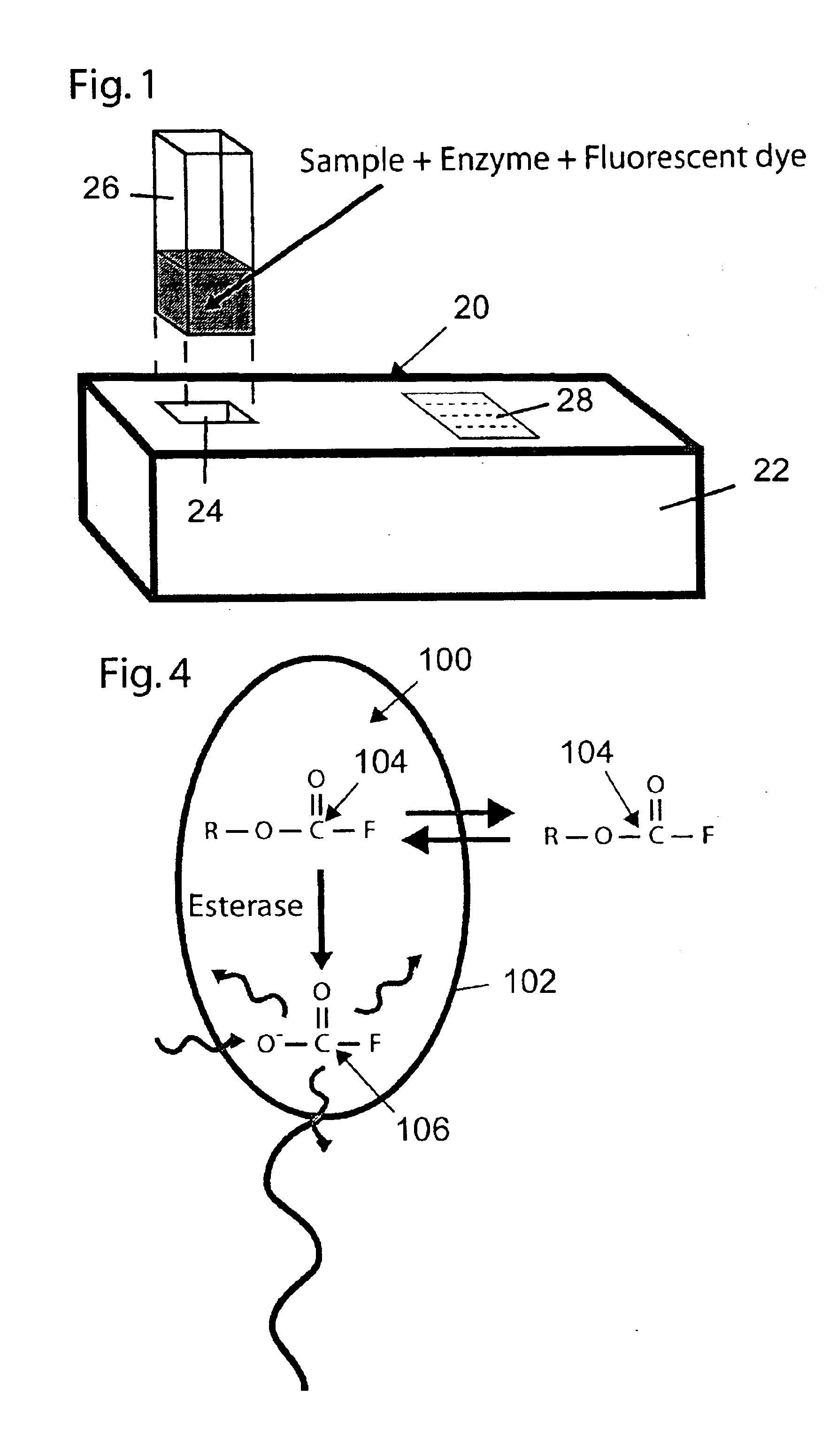
[0074]This section describes components of device constructed in accordance with the invention, in which sperm motility and density characteristics are measured by a pair of optical detectors positions at spaced apart location along a microfluidics channel. The device is illustrated in particular with respect to FIG. 1, which shows external housing features common to all three embodiments of the invention, FIG. 4, which illustrates fluorescence labeling of sperm cells, shows FIGS. 8A-8C, which illustrate microfluidic channel and optical-sensing components of the embodiment, FIG. 9, showing a flow diagram of the electronically controlled algorithm carried out by the device, and FIG. 12, which illustrates two exemplary output displays that are common to all three embodiments.

[0075]FIGS. 8A and 8B illustrate a portion of a microfluidics structure 140 in the second-embodiment device. Shown here are a sample-receiving reservoir 142, and an portion of a microchannel 144 whose upstream end...

third embodiment

[0093]2. Either the graduated cylinder or a separate container with a smaller volume or diluted volume or semen mixed with other chemicals, compounds, or solvents is placed into the sample-receiving well of the device. The insertion of the sample holder is locked into place when it is snapped down into the well, the device electronics are activated, and a sharpened access port perforates the bottom of the sample holder giving the internal device fluid channel access to the semen sample. The semen sample flows into a dry loading reservoir or comes into immediate contact with a pre-filled fluid channel. Alternatively, the treated sample could be poured into the sample collection well after the microchannel is unsealed. In the first two embodiments described, sample pretreatment includes labeling the sample sperm with a fluorescence reporter. In the third embodiment, no sample labeling is required.

[0094]3. If the prefilled fluid channel is kept separate from a dry loading reservoir, di...


PUM

PropertyMeasurementUnit
depthaaaaaaaaaa
widthaaaaaaaaaa
depthaaaaaaaaaa

Abstract

A method and device for assaying sperm motility in a forward direction and density of active sperm in a semen sample are disclosed. The device includes a microfluidics structure having a sample reservoir, a downstream collection region and a microchannel extending therebetween. The microchannel is dimensioned to confine sample sperm to single-direction movement within the channel, such that sperm in a semen sample placed in the sample reservoir enter and migrate along the microchannel toward and into the collection region. Also included is a detector for detecting the presence of labeled sperm in the microchannel or collection region, and an electronics unit operatively connected to the detector for (i) receiving detector signals, (ii) based on the detector signals received, determining sperm motility and density in the sperm sample, and (iii) displaying information related to sperm motility and density.

Description

[0001]This application claims the priority of U.S. Ser. No. 60 / 511,798 filed on Oct. 16, 2003, and U.S. Ser. No. 60 / 431,872 filed on Dec. 9, 2002, both of which are incorporated in their entirety herein by reference.FIELD OF THE INVENTION[0002]The present invention relates to a method and device for assaying male fertility, and in particular, to a method and device for determining sperm motility in a forward direction, and the density of active sperm.BACKGROUND OF THE INVENTION[0003]Couples in the United States and the other industrialized countries have between a 15-20% likelihood of failing to conceive children without some medical intervention. Male Factor Infertility is directly responsible for approximately one-third and a contributing factor in over half of failed conceptions. In order to plan the most appropriate medical interventions, the status of the male semen sample must be accurately determined. According to the World Health Organization criteria for male fertility, the...

Claims


Application Information

Patent Timeline
Patent Type & Authority Patents(United States)
IPC IPC(8): B01L3/00G01N15/14G01N21/64C12M1/26
CPCB01L3/502715G01N15/1459G01N15/1484G01N21/6428G01N21/645B01L2400/0677G01N2015/1075Y10S435/808G01N33/483G01N15/14G01N33/48
Inventor ARAVANIS, ALEXANDER M.PYLE, JASON L.
Owner QN DIAGNOSTICS LLC
Why Eureka
Try Eureka