Electromagnetic brake cooling structure of phase variable device in car engine

a technology of electromagnetic brake and cooling structure, which is applied in the direction of valve drives, braking discs, couplings, etc., can solve the problems of loss of frictional torque generated, and achieve the effects of good abrasion resistance, excellent durability, and large frictional (retarding) torqu

Inactive Publication Date: 2005-08-23
NITTAN VALVE CO LTD
View PDF11 Cites 10 Cited by
  • Summary
  • Abstract
  • Description
  • Claims
  • Application Information

AI Technical Summary

Benefits of technology

[0019](FUNCTION) In this arrangement, the sprocket to which the driving power of the engine is transmitted by a crank shaft is adapted to rotate integrally with, and in synchronism with, a camshaft that functions as a valve mechanism, in such a way that when a retarding force is acted on the rotational drum by the electromagnetic brake means, the drum is delayed in rotation behind the sprocket, resulting in a change in phase of the camshaft with respect to the sprocket. Engine oil is introduced to the sliding sections of the friction member and the rotational drum via an oil passage formed in the camshaft, an oil sump provided formed in a radially small section of the clutch case, and the oil lead-in notches formed in the leading edge of the inner peripheral wall of the clutch case in order to cool the sliding surfaces of the friction member and the rotational drum. It should be noted that the engine oil is supplied to and drained from the sliding surfaces of the friction member and the rotational drum at a higher flow rate via the oil lead-out notches formed in the leading edge of the outer circular wall of the clutch case to enhance the drainage of the oil from the sliding sections to the outside of the clutch case, which facilitates cooling of the sliding surfaces. That is to say, the amount of oil introduced into the sliding sections is increased by the amount led out of the sliding sections, resulting in enhanced circulation of the engine oil through the sliding sections and corresponding cooling effect on the friction member and the rotational drum.
[0031](FUNCTION) Since the porous member thus formed has more than 80 volume percent of all pores being in the range from 5 to 100 μm in pore size, it is less likely to be clogged, thereby creating a large frictional (retarding) torque acting on the disc surface of the rotational drum. In addition, the friction member has good abrasion resistance and hence excellent durability.

Problems solved by technology

This apparatus has a drawback in that when the sliding surfaces of the friction member 4d of the housing 4b and the rotational drum 5 are heated to a high temperature due to friction between them, the surface of the friction member 4d which is generally made of a porous material is clogged with deposits of antioxidant, friction modifier, reactants of additives such as detergent dispersant, and insoluble compositions dispersed in the engine oil, thereby losing frictional torque generated between the friction member 4d and the rotational drum 5.

Method used


Image

  • Electromagnetic brake cooling structure of phase variable device in car engine
  • Electromagnetic brake cooling structure of phase variable device in car engine
  • Electromagnetic brake cooling structure of phase variable device in car engine

Examples


second embodiment

[0063]In the second embodiment shown herein, the friction member 66A is made of a non-woven fabric of carbon fiber impregnated with a heat-hardening resin to form a porous member with more than 80 volume percent of all the pores having pore diameters in the range of 5-100 μm.

[0064]This porous member has large pores that are less likely to be clogged, and hence the friction member 66A has excellent durability. This implies that the friction member 66A can maintain a large frictional force (retarding torque) that act on the disk face of the rotational drum over a long period.

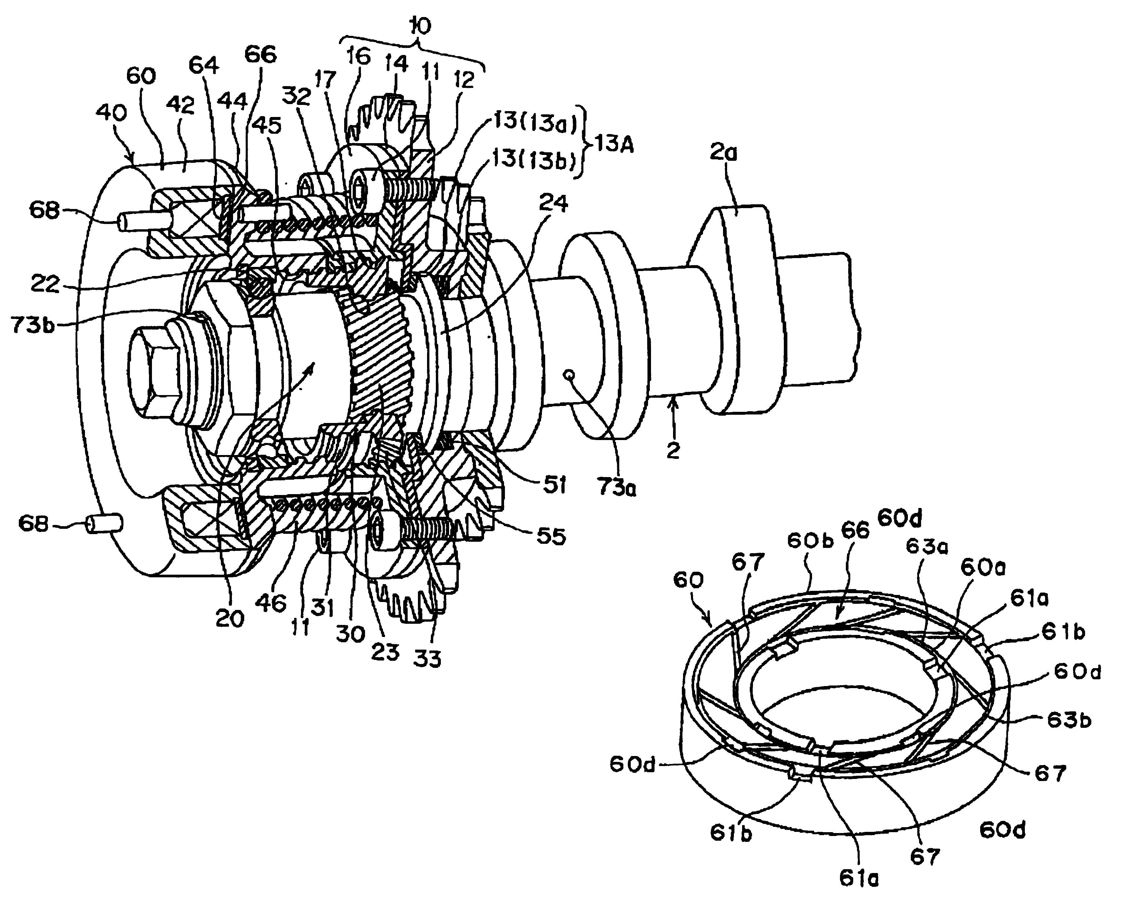
[0065]Formed in the surface of the friction member 66A are gridironed oil grooves 67a capable of supplying engine oil uniformly over the entire surface of the friction member 66A.

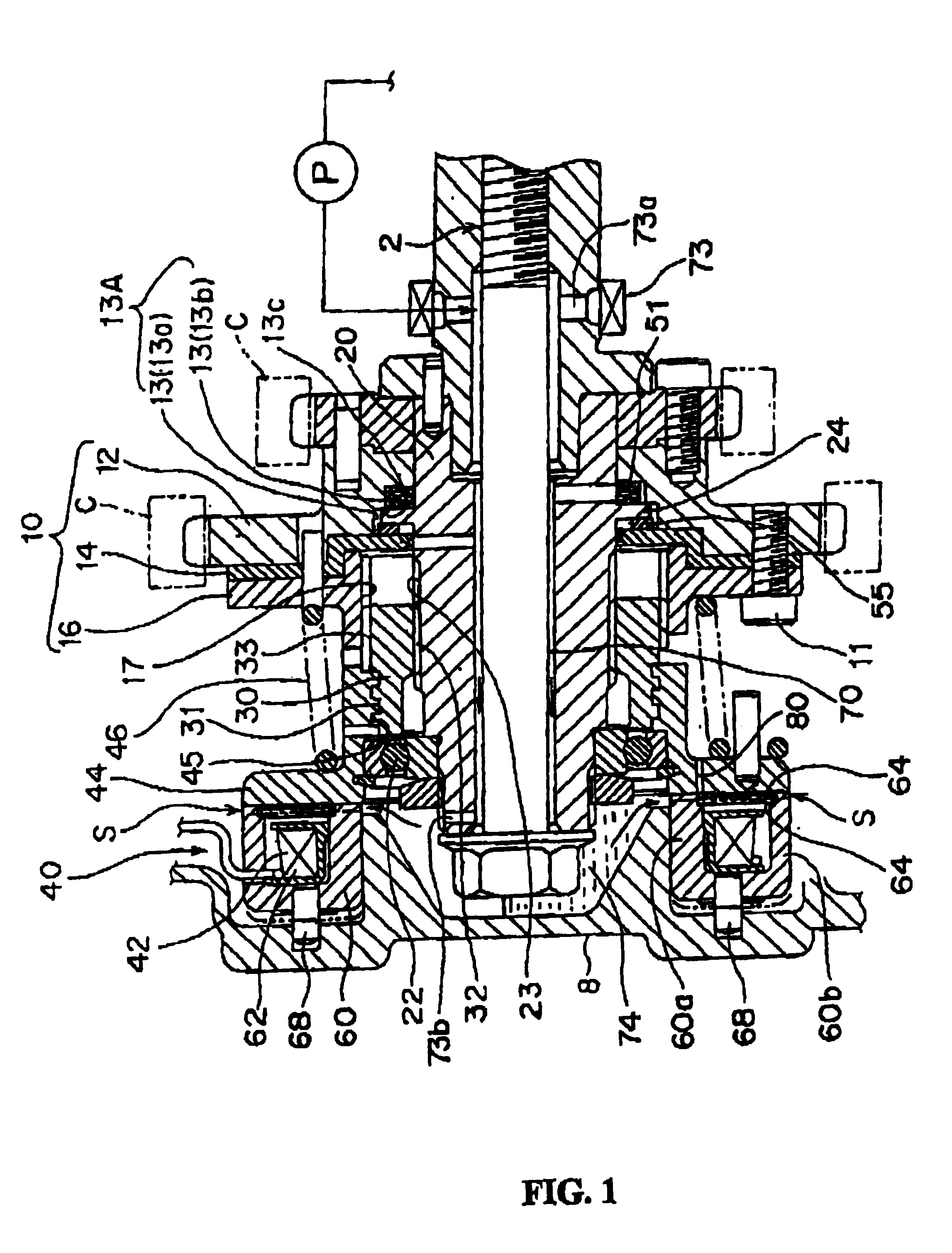
[0066]On the other hand, the rotational drum 44 is provided on the disk surface thereof with an annular oil passage 82. In addition, the oil passage 82 has a multiplicity of oil lead-out holes 80 which enhance faster flows of oil.

[0067]Ac...

first embodiment

[0069]This embodiment is the same in the rest of the structure as the Hence, further details of the like components will be omitted.

[0070]FIGS. 9 and 10 together show a third embodiment of a phase varying apparatus for use with an automobile engine. Particularly, FIG. 9 is a front view of an electromagnetic clutch, which is a main portion of the apparatus. FIG. 10 is a perspective view of a rotational drum, which is another main portion of the apparatus. Like components in the first and the second embodiments are identified by like reference numerals.

third embodiment

[0071]In the third embodiment shown herein, the friction member 66B is made of a non-woven fabric of aramid fiber impregnated with a heat-hardening resin to form a porous member with more than 80 volume percent of all the pores having pore diameters in the range of 5-100 μm.

[0072]This porous member has large pores that are less likely to be clogged, and hence the friction member 66B can create a large frictional force (retarding torque) that act on the disk face of the rotational drum. In addition, the friction member 66A has a good durability that it can maintain such large frictional force over a long period.

[0073]The friction member 66B is provided on the disk surface thereof with radial oil grooves 67b for uniformly providing engine oil over the entire surface of the friction member 66B.

[0074]Although the rotational drum 44 is provided on the disk surface thereof with an annular oil passage 82, it is not provided with oil lead-out holes such as ones 80 of the first and second em...


PUM


Abstract

An electromagnetic-brake cooling structure of a phase-variable device having an electromagnetic brake means (40) and varying the phase of a camshaft, wherein engine oil in an oil sump (74) on the radial inner side of a clutch case (60) led to the relative sliding surfaces of a friction material (66) and a rotary drum (44) through a notch (61) provided in the clutch case (60) at the front edge part of the inner peripheral wall of the clutch case (60), a notch (61b) for leading oil to the front edge part of the clutch case outer peripheral wall (60b), the oil on the relative sliding surfaces of the friction material (66) and the rotary drum (44) is discharged positively to the outside, and the circulation of the cooling oil is activated to increase the cooling effect of the sliding surface of the friction material (66).

Description

FIELD OF THE INVENTION[0001]The invention relates to a cooling structure of an electromagnetic brake of a phase varying apparatus for use with an automobile engine, adapted to vary the valve timing of the engine by applying a retarding or braking force onto a rotational drum of the phase-varying apparatus by electromagnetic break means to vary the rotational phase of the camshaft of the engine relative to the sprocket. More particularly, the invention relates to a cooling structure for cooling an electromagnetic break means that provides a retarding force on the rotational drum of a phase-varying apparatus by circulating engine oil through the apparatus.BACKGROUND OF THE INVENTION[0002]This type of phase varying apparatus is disclosed in, for example, Japanese Patent Early Publication H4-272411. This apparatus has a movable plate 3 mounted between a drive member (sprocket) 1, to which driving power of a crank shaft of the engine is transmitted, and a camshaft 2 of a valve mechanism,...

Claims


Application Information

Patent Timeline
Patent Type & Authority Patents(United States)
IPC IPC(8): F01L13/00F01L1/344F01L1/34F01P3/12F01P3/00F16D55/06F16D65/12F16D65/78F16D69/00
CPCF01L1/022F01L1/34F01L1/344F01L1/34406F01L2001/0537F01L2201/00F01P3/12
Inventor AINO, HIROSHIHONMA, KOICHIMOROZUMI, HIROKIMAE, YOUSUKEMUKAI, KAZUHITO
Owner NITTAN VALVE CO LTD
Why Eureka
Try Eureka