
Reciprocal blade lapping machine

a blade lapping machine and blade technology, applied in the field of blade lapping machines, can solve the problem of easy damage of blades, and achieve the effect of convenient cleaning and maintenan

Inactive Publication Date: 2005-08-23
HUNT ROY H
View PDF28 Cites 17 Cited by
  • Summary
  • Abstract
  • Description
  • Claims
  • Application Information

AI Technical Summary

Benefits of technology

[0013]Lapping machines have been used for decades to obtain a very fine flat surface for items that mate together to form a seal, cutting surface, flat interface or other items requiring an extremely smooth surface. The usual purpose is to maintain an exceptionally flat face; however some mating surfaces function better if a minute or minuscule radial surface is provided. Such is the case with cutting devices that use a pair of mating blades therefore it is the primary object of the invention to obtain an extremely precise surface on the matched top (cutter) and bottom (comb) of a blade sets that function best when the convex surface of the cutter blade closely glides across the convex surface of the comb.
[0014]The present invention is best appreciated when used on the cutting surfaces of livestock clippers such as manufactured by Lister, Oster and Andis as well as human hairdressing clippers used universally in barber shops and hair dressing salons produced by Wahl, Oster and Andis etc. In order to provide this long felt need, the invention achieves the results by the use of a convex shaped lapping plate and a reciprocating work piece holder that slideably rests upon the lap plate and alternately slides the blade set backward and forward in a straight line aligned with the center of the rotating lap plate convex upper surface. Since the set is positioned side by side, the radius of the lap plate is duplicated on the cutting surfaces of the blade set as the set is continually moving across the face of the lap plate which provides accurate replication. The work piece holder not only locates and holds the blade set in place but also provides the precise amount of pressure in an adjustable and repeatable manner.
[0015]It is a common practice to sharpen clipper blades using a persons fingers to hold the blade against a moving wheel. With this manual procedure blades are easily damaged from uneven grinding, overheating and accidental mishaps. Even when damage is not apparent blade life and duration of sharpness may be considerably shortened. The invention is different from hand lapping, as uneven grinding and heating is eliminated since the lapping plate rotates slowly and the blade set is simultaneously moved by mechanical means in a linear direction across the revolving plate. Further a measured amount of fine grit mixed with oil is dripped onto the convex plate in front of the blade set being sharpened. The amount of weight pressing down on the blade set is precisely, governed by spring loading rather than by finger touch.
[0017]Still another object of the invention is that the work piece holders may be turned end for end to compensate for irregular erosion on one of the pair of wear plates that position the holder above the lapping plate, as they rest on the revolving lapping plate and may wear unevenly in time.
[0019]A final object of the invention is directed to the improvement in the drainage of the compound from the lap plate over the prior art as a fiberglass drain pan is positioned directly under the lap plate and is configured to receive the waste compound and direct it into a container at the rear of the lapping machine by gravity. The configuration permits the entire liquid compound distributed on top of the lap plate to be received and drained since its configuration allows the pan to almost touch the bottom of the lap plate and is exposed on the periphery allowing ease of cleaning and maintenance.

Problems solved by technology

With this manual procedure blades are easily damaged from uneven grinding, overheating and accidental mishaps.

Method used


Image

  • Reciprocal blade lapping machine
  • Reciprocal blade lapping machine
  • Reciprocal blade lapping machine

Examples


Embodiment Construction

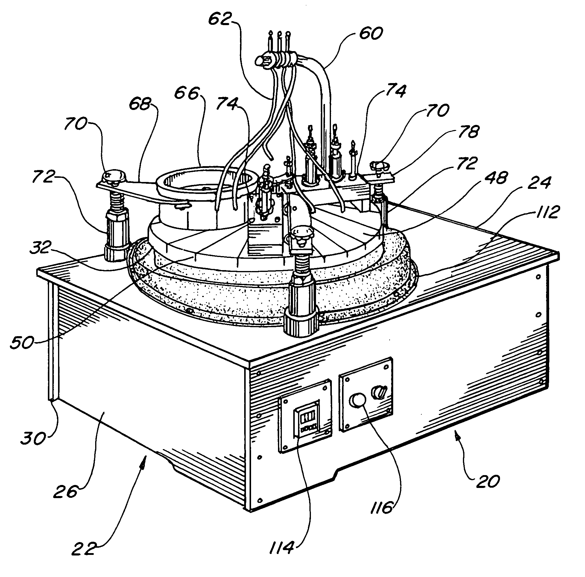
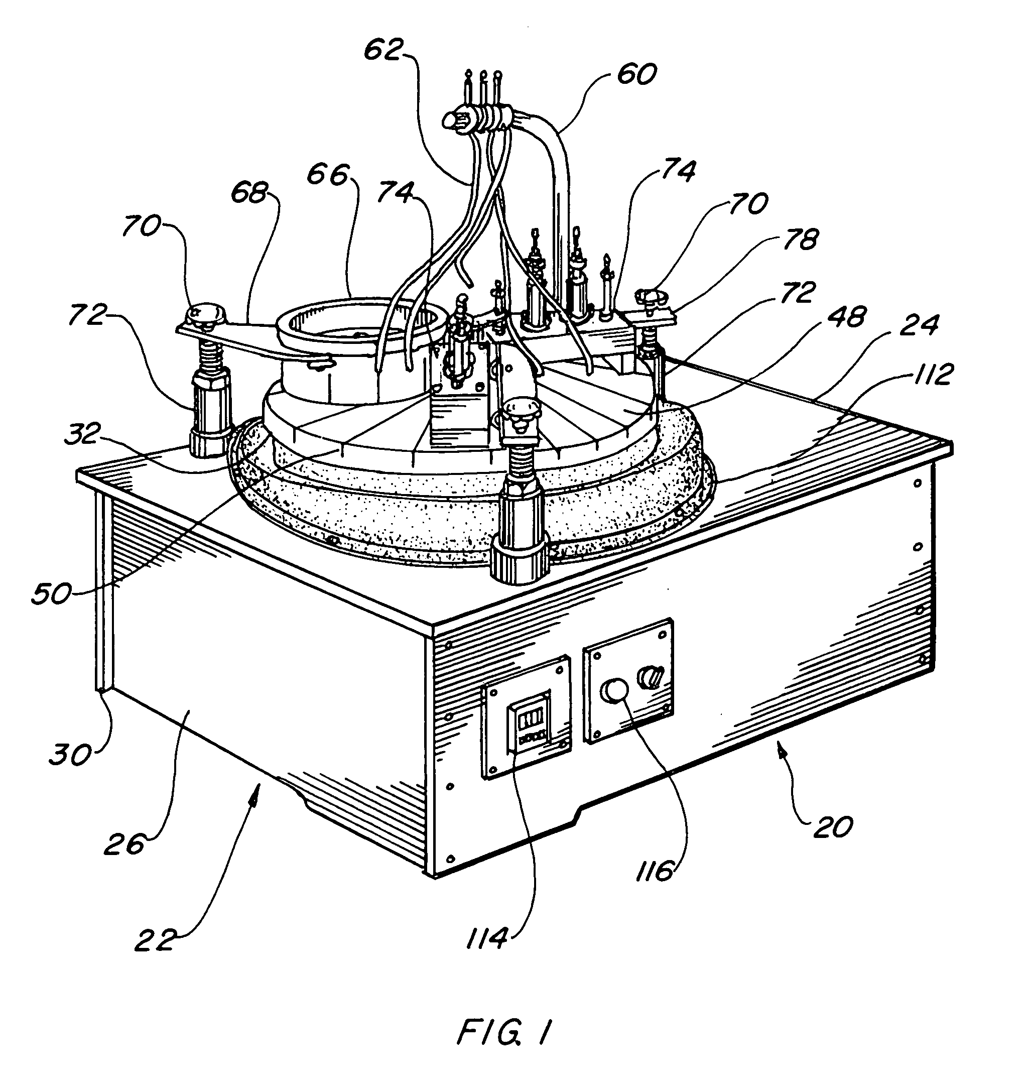
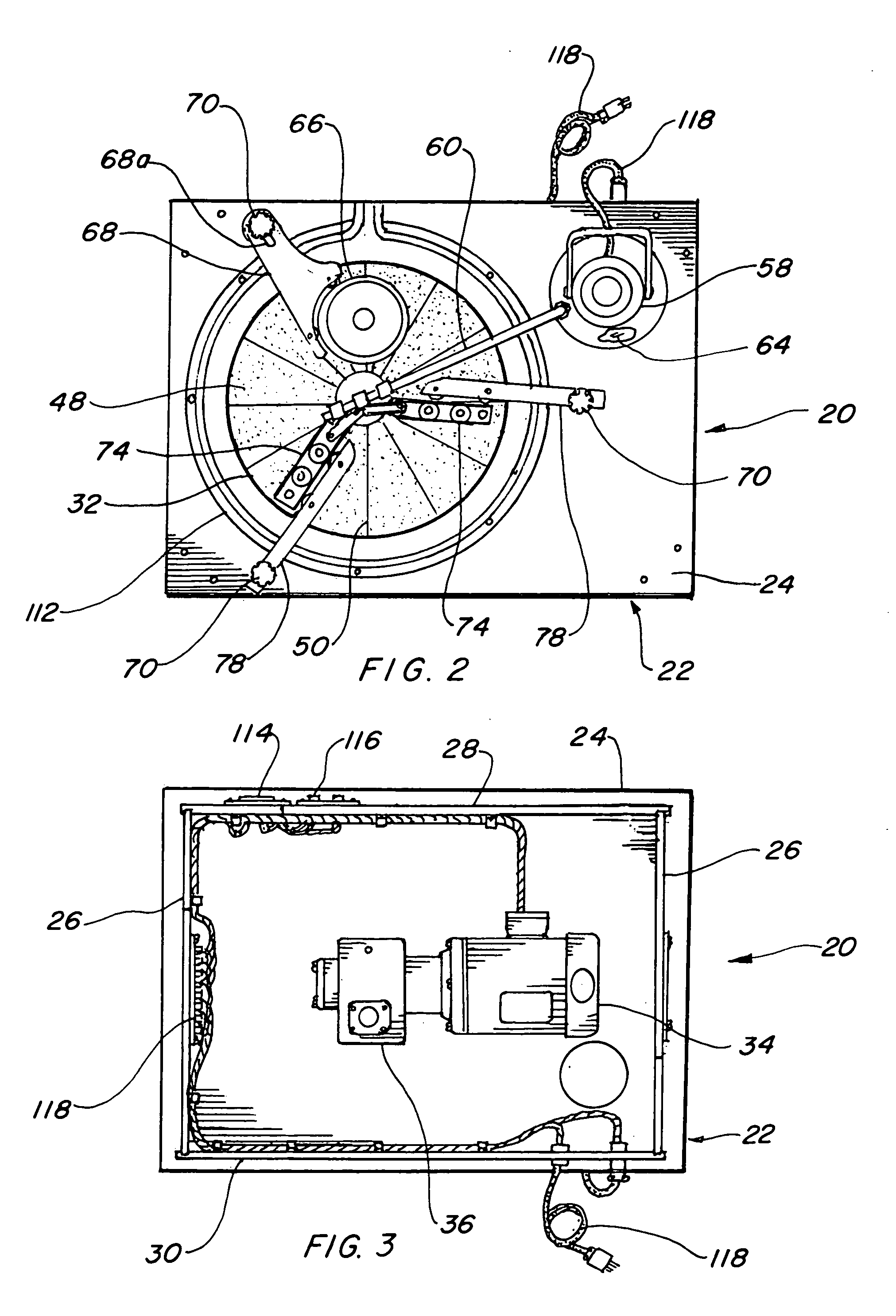
[0034]The best mode for carrying out the invention is presented in terms of a preferred embodiment. This preferred embodiment of the blade lapping machine 20 is shown in FIGS. 1 thorough 13 and is comprised of an enclosure 22 having a rigid top 24, sides 26 a front 28 and a back 30. The elements of the enclosure 20 are preferably a plurality of aluminum plates bolted together to form this rigid structure however any other material and type of fabrication may be equally well suited as long as it has structural integrity and is robust and rigid. It is preferred that the plates are recessed into grooves at the interfacing joints to achieve the maximum strength.

[0035]Drive means, as illustrated in FIG. 7, are attached to the enclosure top 24, for rotating a lap plate 32 and consist of the following; an electric motor 34, a worm gear speed reducer 36 interfacing with the electric motor 34 and a lapping plate mounting hub 38 attached to an output shaft of the speed reducer 36. A bearing 4...


PUM

PropertyMeasurementUnit
Diameteraaaaaaaaaa
Diameteraaaaaaaaaa
Pressureaaaaaaaaaa

Abstract

A reciprocal blade lapping machine (20) is taught that is used for sharpening cutting and shearing blades. The lapping machine consists a convex lap plate (32) mounted on an enclosure (22) rotated by an electric motor (34) connected to a speed reducer (36). A lapping compound distribution system is positioned directly above the lap plate and disperses lapping compound (64) onto the convex upper surface (48) of the lap plate providing an abrasive media for removing parent material from a set of blades placed on the lap plate. A conditioning ring (66), including dead weigh within, is rotatably disposed on the lap plate impacting directly upon the rotating lap plate maintaining the convex contour. A pair of reciprocating work piece holders (74) slideably rest on the lap plate, and alternately slide work pieces (76) backward and forward in a straight line on the rotating lap plate upper surface. Matched set of work pieces (76) are retained by the work piece hold downs (98) located within the work piece holders against the convex surface of the rotating lap plate, for sharpening by honing the mating cutting faces of the work pieces.

Description

TECHNICAL FIELD[0001]The present invention relates to lapping machines in general. More specifically to a blade lapping machine with work holders sliding blade sets linearly to and fro across a rotating convex lap plate.BACKGROUND ART[0002]Previously, many types of lapping machines have been used in endeavoring to provide an effective means to obtain a smooth lapped surface or to sharpen objects having a flat face. Many patents have been issued to special purpose lapping machines for specific purposes and to accelerate manufacturing processes.[0003]The prior art listed below did not disclose patents that possess any of the novelty of the instant invention; however the following U.S. patents are considered related:[0004]U.S. Pat. No.InventorIssue Date2,627,144RoshongFeb. 3, 19532,782,571HansonFeb. 26, 19573,004,371Layton et al.Oct. 17, 19614,502,252IwabuchiMar. 5, 19854,805,348Arai et al.Feb. 21, 19894,916,868WittstockApr. 17, 19905,099,614Arai et al.Mar. 31, 19926,511,365Terashima e...

Claims


Application Information

Patent Timeline
IPC IPC(8): B24B3/36B24B3/00B24B3/60B24B37/04
CPCB24B3/361B24B3/60B24B37/102B24B37/30
Inventor HUNT, ROY H.
Owner HUNT ROY H
Learn More