Microfabricated chemical reactor

a chemical reactor and micro-fabricated technology, applied in chemical/physical/physical-chemical process catalysts, metal/metal-oxide/metal-hydroxide catalysts, metal/metal-oxide/metal-hydroxide catalysts, etc., can solve the problems of difficult precision control, non-stoichiometric portions, and regions of reaction mixtures, so as to reduce the pressure drop through the reactor and efficiently react the reaction components

Inactive Publication Date: 2005-08-23
MASSACHUSETTS INST OF TECH
View PDF22 Cites 75 Cited by
  • Summary
  • Abstract
  • Description
  • Claims
  • Application Information

AI Technical Summary

Benefits of technology

[0015]The present invention also is directed to a microfabricated chemical reactor having a plurality of laminae with an inlet port and an outlet port and a continuous channel including a plurality of channels forming a reaction zone and providing fluid communication between the inlet port and the outlet port. The plurality of channels forming the reaction zone may provide a surface to volume ratio suitable to efficiently react the reaction components, while also providing for a relatively lower pressure drop through the reactor.

Problems solved by technology

Certain chemical reactions occur rapidly and, therefore, are particularly difficult to control with precision.
Inadequate mixing may lead to regions of the reaction mixture including non-stoichiometric portions of reactants, reaction hot spots, reaction dead spots due to channeling, formation of unwanted byproducts, or production of products other than those desired.
The above problems may be particularly evident when reactions are carried out on a large scale, with relatively large volumes of reaction components.
The large size of these reactors makes controlling high rate chemical reactions especially difficult.
Incomplete and inefficient mixing may also affect controlling the temperature of a reaction.
Localized hot spots due to a high concentration of reactants typically lead to product degradation and by-product formation.
Under these conditions, undesired secondary reactions may occur which produce undesired byproducts, reduce the overall efficiency of the reaction, and create downstream purification problems.
The limitations of conventional industrial and laboratory reactor systems may be primarily attributed to the small surface to volume ratio present in the reactors.
This ratio greatly reduces mixing efficiency, and uniform temperature control of the entire volume of chemical reactants is difficult.
Although the high surface to volume ratios of miniature chemical reactors offer improvements in thermal management and mass transfer, designing reactors of this type also presents challenges resulting from greatly increased pressure drop across channels having dimensions that may be on the order of tens of microns.
These pressure drop considerations result in increased energy costs and limitations on the overall production rate of the reactor.
Uneven flows can lead to incomplete utilization or local zones of varying reaction rate and heat transfer.
Poor distribution of the fluids can thus lead to local “hot spots” which can decrease the reaction selectivity, reduce catalyst life, or lead to side reactions which may lead to dangerous uncontrollable side reactions.
In addition to losses in selectivity and decreased product yield, poor thermal management can decrease the life of a catalyst and further reduce the efficiency of a reactor.
The associated flammability danger of oxidation reactions precludes the use of organic solvents or high concentrations of oxygen.

Method used


Image

  • Microfabricated chemical reactor
  • Microfabricated chemical reactor
  • Microfabricated chemical reactor

Examples


example 1

[0060]A first design of a microfabricated reactor within the present invention has been adapted to the chemistry of heterogeneous catalytic reactions. For such reactions, the high surface areas of traditional porous catalytic supports allow for a greater dispersion of the active surface sites and consequently, a higher reaction rate per volume of support. For heterogeneous catalytic reactions of moderate rate, such as some hydrogenations, processing in small volumes requires the highest attainable active surface area in order to have a practical reactor production rate. Planar metal films, while easy to integrate into microfabricated reactor designs using known thin film application methods, cannot attain the same active area as traditional catalyst particles through geometry alone. Therefore, while thin film catalysts may be sufficient for fast gas-phase reactions, such as ammonia oxidation, higher surface area catalysts can extend the range of applicable reactions in the microenvi...

example 3

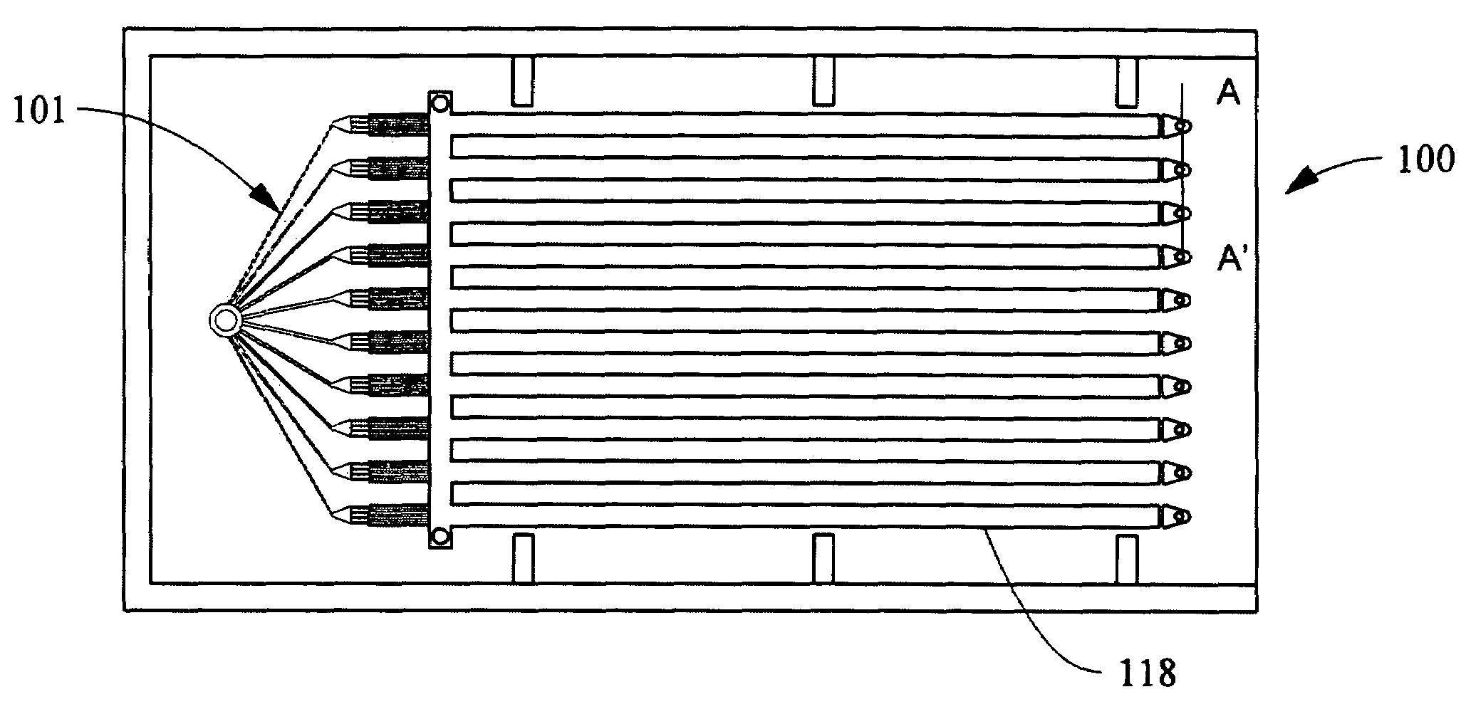
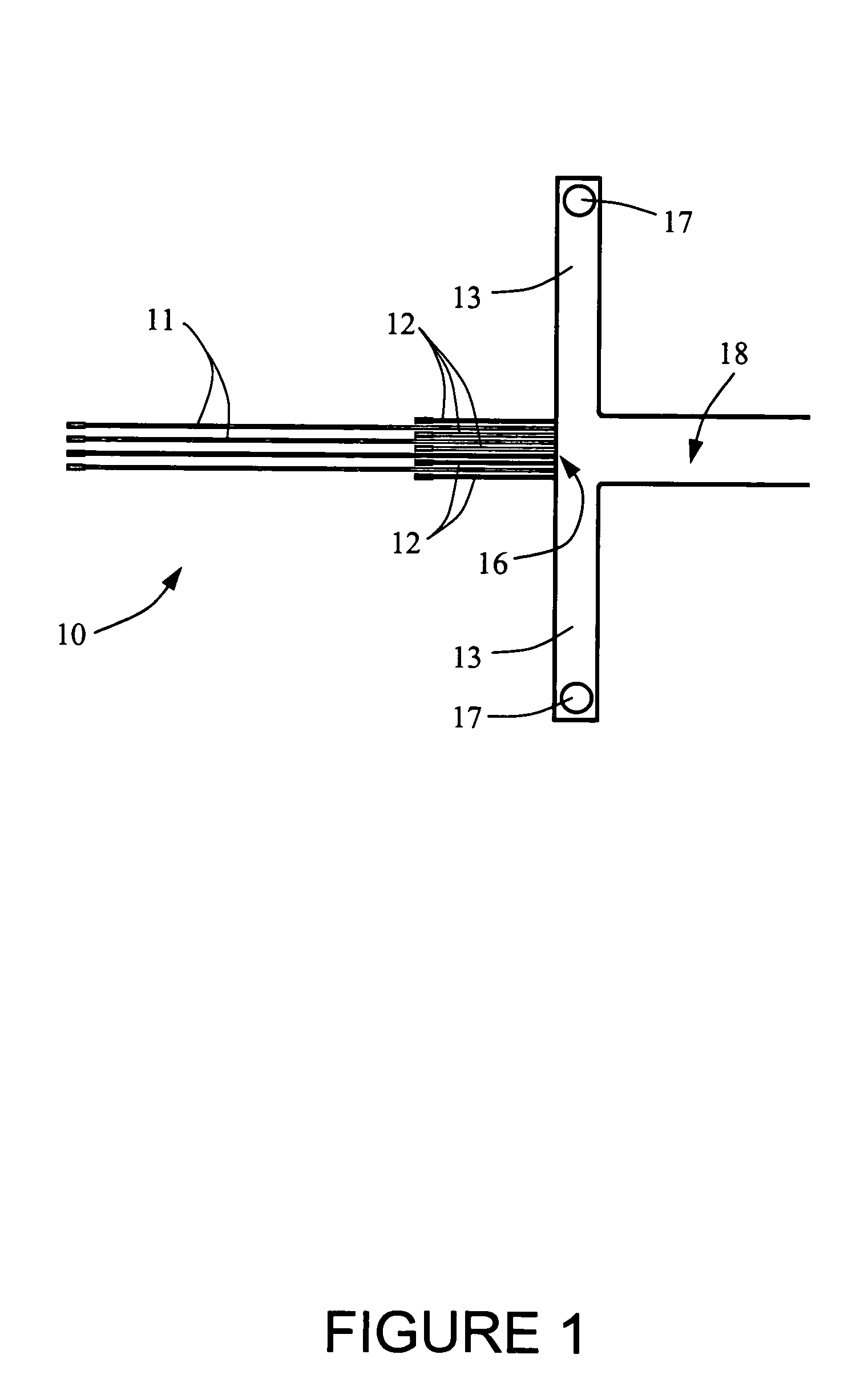
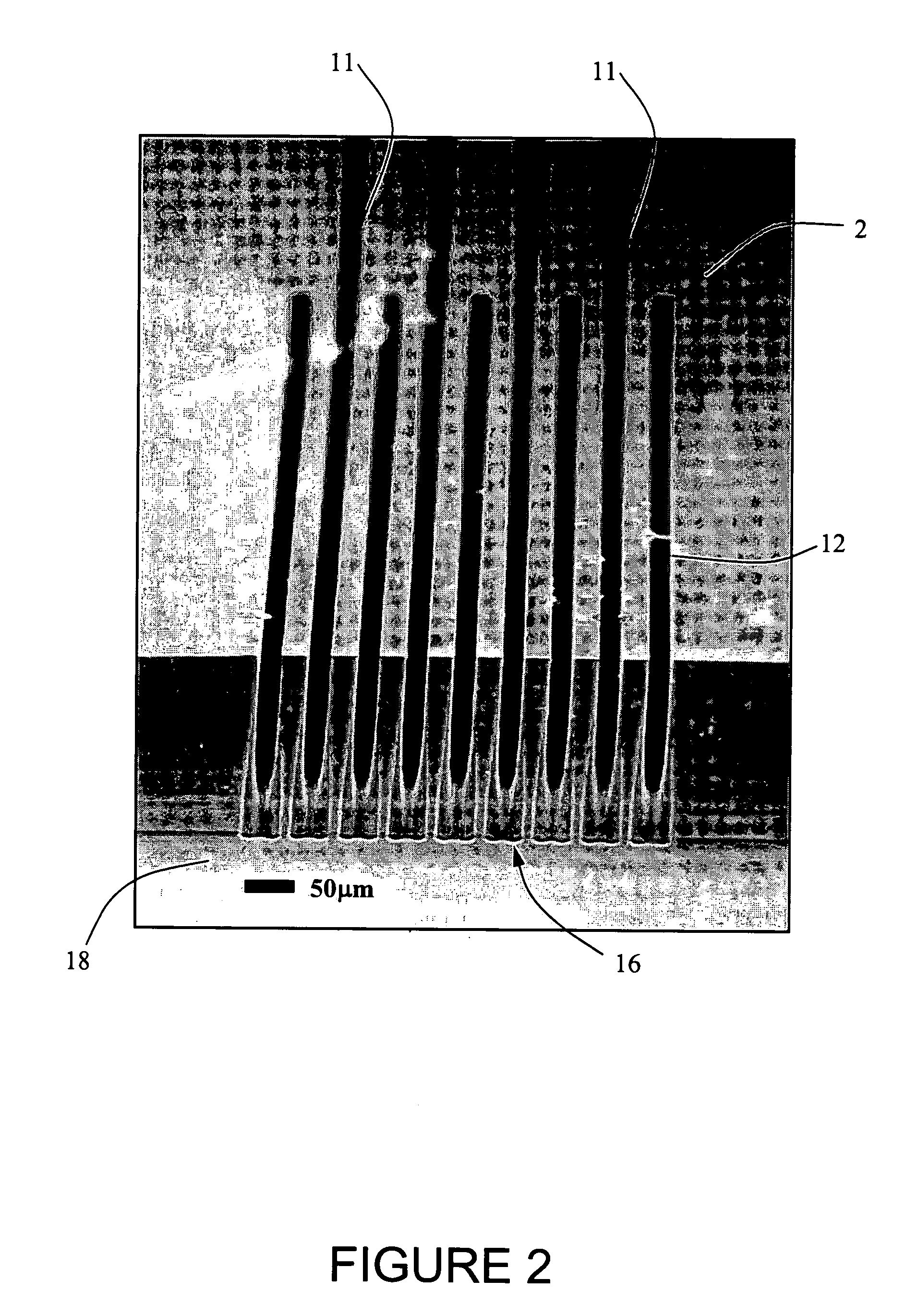
[0095]As seen in FIG. 22 an array of 10 reaction channels 431 may be fabricated in silicon and may be connected through an array of on-chip microfluidic distribution channels. The gas inlet 436 may pass through a manifold 433 comprising 10 channels having widths that vary depending on the length to ensure an even distribution of flow to each reaction channel 431. The liquid inlet is split among the channels in a layer below the first layer that is depicted in FIG. 22 and meet the gas inlets in an interleaving fashion to provide a microfluidic manifold, an embodiment of which is shown in FIGS. 1 and 2. The reaction channels of reactor 430 are 2 cm long and 600 μm wide. The ten reaction channels 431 of reactor 430 contain integrated catalyst support structures 440, as seen in the photomicrograph of FIG. 23, that are posts 50 μm in diameter and 300 μm tall, and which are arranged in a staggered array. The void fraction of a catalyst of this design is 60%. Compared with packed-beds, whi...


PUM

PropertyMeasurementUnit
diameteraaaaaaaaaa
diameteraaaaaaaaaa
diameteraaaaaaaaaa

Abstract

A microfabricated chemical reactor includes a plurality of lamina, an inlet port formed in at least one of the lamina, and an outlet port formed in at least one of the lamina. A continuous channel is formed in at least one of the lamina and provides fluid communication between the inlet port and the outlet port. In one configuration of the microfabricated chemical reactor, the reactor includes a particle filter disposed in the continuous channel and formed by one of the lamina, wherein the particle filter restricts flow through the continuous channel and retains catalyst or other particles within the continuous channel.

Description

CROSS-REFERENCE TO RELATED APPLICATIONS[0001]This application claims priority under 35 U.S.C. § 119(e) from U.S. Provisional Application Ser. No. 60 / 162,621, filed Oct. 29, 1999.FEDERALLY SPONSORED RESEARCH[0002]This invention was made with support under DARPA Contract No. F30602-97-01 00.TECHNICAL FIELD AND INDUSTRIAL APPLICABILITY OF THE INVENTION[0003]The present invention relates to microfabricated chemical reactors. Microfabricated chemical reactors find particular application in conducting chemical synthesis, and such devices find particular application in conducting heterogeneous catalytic reactions involving gas and liquid reactants.DESCRIPTION OF THE INVENTION BACKGROUND[0004]Process miniaturization and micro-reactor technology provide opportunities for improving chemical processing and provide improved process control in chemical synthesis. Smaller scale chemical reactors may allow safer and more efficient investigation of the kinetics of chemical reactions. Recent work ha...

Claims


Application Information

Patent Timeline
Patent Type & Authority Patents(United States)
IPC IPC(8): B01J8/02B01J35/00B01J35/02B01J19/00
CPCB01J19/0093B01J23/42B01J35/0006B01J2219/00783B01J2219/0081B01J2219/00828B01J2219/00835B01J2219/0086B01J2219/00862B01J2219/00873B01J2219/00889B01J2219/00891B01J2219/00909B01J2219/00961B01J2219/00963B01J2219/00984B01J2219/00995
Inventor LOSEY, MATTHEW W.JENSEN, KLAVS F.SCHMIDT, MARTIN A.
Owner MASSACHUSETTS INST OF TECH
Why Eureka
Try Eureka