Method and apparatus for reading reporter labeled beads

Inactive Publication Date: 2005-08-23
AMNIS CORP
View PDF53 Cites 63 Cited by
  • Summary
  • Abstract
  • Description
  • Claims
  • Application Information

AI Technical Summary

Benefits of technology

[0017]In accord with the present invention, a method and apparatus for imaging and reading reporter labeled beads are provided. The method and apparatus of the present invention enable individual encoded beads to be imaged, and the compound attached to that bead to be identified as a function of image data, so that the identity and sequence of all sub units of the compound are determined. Generally, a single encoded bead will include redundant copies of the same compound and the associated reporters. In one preferred appli

Problems solved by technology

While SNPs are abundant, an individual SNP is not rich in information.
Nevertheless, the limitations of conventional microscopy techniques impose the requirement that beads be affixed to a substrate prior to analysis, thereby adding numerous preparatory steps to bead-based assays.
These preparatory steps add time and expense, while simultaneously reducing the flexibility and utility of bead-based analytical processes.
Although autofocus systems are well known in the art, the focus step requires additional time, expense, and adds variability to the process.
In addition, if the signaling molecules or reporters are randomly distributed on the beads, it may not be possible to identify signals or signatures from a fraction of the beads due to the absence of the signals or reporters from the planar FOV.
The planar substrate preparation presents only one, or at most two, of six possible perspectives from which

Method used


Image

  • Method and apparatus for reading reporter labeled beads
  • Method and apparatus for reading reporter labeled beads
  • Method and apparatus for reading reporter labeled beads

Examples


first embodiment

for Spectral Decomposition and Imaging

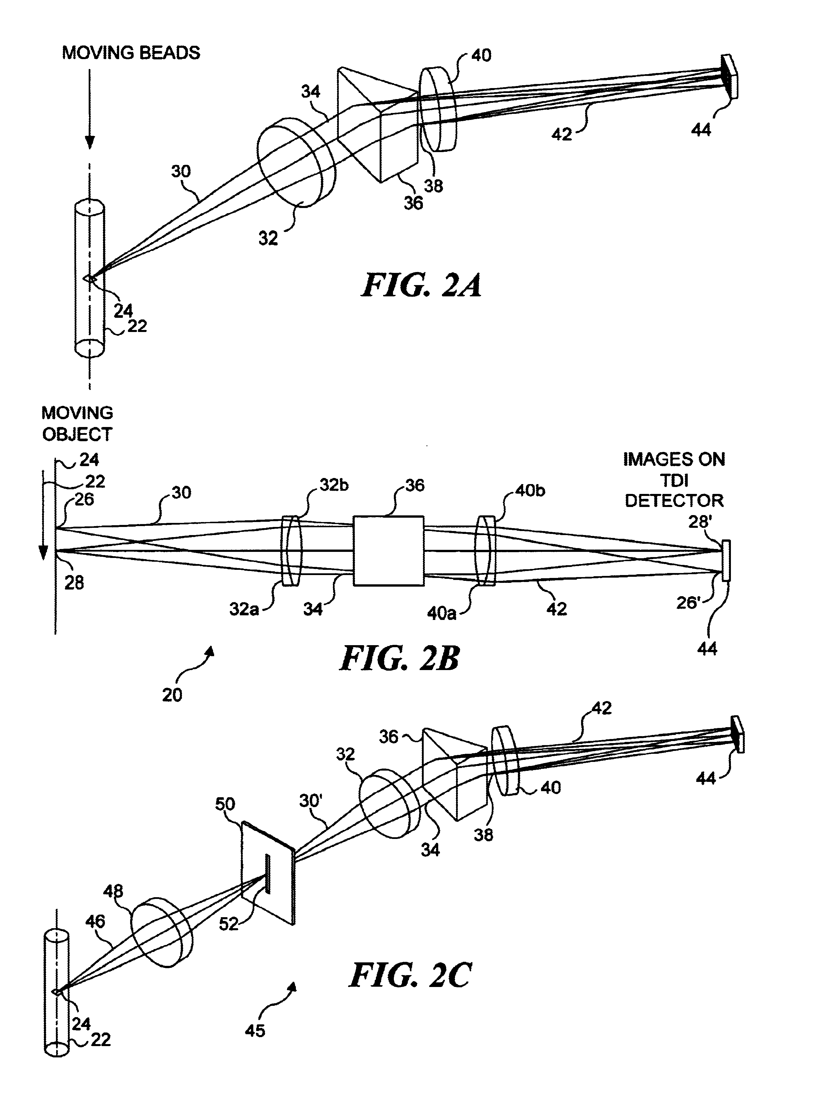
[0071]A first embodiment of the system for spectral decomposition and imaging is shown in FIG. 2A, and this embodiment is also disclosed in commonly assigned U.S. Pat. No. 6,211,955, entitled “Imaging and Analyzing Parameters of Small Moving Objects Such as Cells,” filed on Mar. 29, 2000, the drawings and disclosure of which are hereby specifically incorporated herein by reference. In this previously filed application, there is no discussion of identifying reporters on beads. However, the following discussion describes how the apparatus disclosed in this previously filed application can be employed for spectral decomposition and imaging of objects such as beads and reporters included thereon. In regard to the present invention, a bead provided with reporters is simply a specific type of object. (It should be noted that where there is any variance between the description in any document incorporated herein by reference and the present disclosure,...

second and third embodiments

of Apparatus for Spectral Decomposition and Imaging

[0099]In the second embodiment of apparatus usable in practicing the present invention, a spectral dispersing component having characteristics that ensure no distortion or convolution of the image occurs due to the emission bandwidth is employed, and as a result, a deconvolution step is not needed to process the image data. FIG. 11 illustrates this second preferred embodiment. Unlike a prism, where every wavelength leaves the prism at a different angle, all light within a predefined bandwidth incident on the dichroic beam splitter at a common angle leaves the dichroic beam splitter at the same angle. Consequently, there is no convolution between the emission spectrum of the light leaving the bead and the image of that bead. When using such a spectral dispersing component, light of a first spectral bandwidth is reflected from the first dichroic beam splitter at a predefined nominal angle. Light of a second spectral bandwidth is passe...

fourth embodiment

of Apparatus for Spectral Decomposition and Imaging

[0110]The fourth embodiment of apparatus usable for spectral decomposition and imaging in connection with the present invention, which is illustrated in FIG. 16A, is similar to the second and third embodiments in that no convolution of the emission spectra with the image occurs as a result of the spectral decomposition process. Spectral decomposition occurs in an axis generally perpendicular to flow through the use of dichroic filters as previously described. However, in this embodiment, separate imaging lenses and detectors are used for each spectral region. Dichroic filters 277 are placed at infinity (with respect to the object) after a collection lens 278 to minimize optical aberrations. After each dichroic filter 276a separate imaging lens 280 is used to form an image of the objects onto the corresponding detectors 282. In this configuration, each detector 282 has fewer pixels than other embodiments because each detector covers ...


PUM

PropertyMeasurementUnit
Lengthaaaaaaaaaa
Flow rateaaaaaaaaaa
Coloraaaaaaaaaa

Abstract

Combinatorially-synthesized deoxyribonucleic acid (DNA) oligonucleotides attached to encoded beads that are hybridized to amplified and labeled genomic DNA or ribonucleic acid (RNA) are analyzed using a flow imaging system. Oligonucleotides and corresponding reporters are bound to the surfaces of a plurality of small beads such that different beads bear different oligo sequences. Each bead bears a unique optical signature comprising a predefined number of unique reporters, where each reporter comprises a predefined combination of different fluorochromes. The composite spectral signature in turn identifies the unique nucleotide sequence of its attached oligo chains. This optical signature is rapidly decoded using an imaging system to discriminate the different reporters attached to each bead in a flow in regard to color and spatial position on the bead.

Description

RELATED APPLICATIONS[0001]This application is based on prior copending provisional application Ser. No. 60 / 240,125, filed on Oct. 12, 2000, and prior copending provisional application Ser. No. 60 / 242,734, filed on Oct. 23, 2000, the benefits of the filing dates of which are hereby claimed under 35 U.S.C. § 119(e). This application is further a continuation-in-part of prior conventional application Ser. No. 09 / 939,292, filed on Aug. 24, 2001, now U.S. Pat. No. 6,532,061, which is based on a prior provisional application Ser. No. 60 / 228,076, filed on Aug. 25, 2000, the benefits of the filing dates of which are hereby claimed under 35 U.S.C. §119(e) and under 35 U.S.C. § 120.FIELD OF THE INVENTION[0002]The present invention generally relates to a method and apparatus employed to image an encoded reporter labeled bead, and more specifically, to a method and apparatus that enable encoded reporter labeled beads to be imaged in stasis or when entrained in a flow of fluid, such that imaging...

Claims


Application Information

Patent Timeline
IPC IPC(8): C12Q1/68C40B20/04C40B30/04C40B40/08C40B60/10G01N15/14G02B7/28G02B27/00G02B27/14
CPCC12Q1/6816C40B20/04C40B30/04C40B40/08C40B60/10G01N15/147G01N15/1475G01N2015/1447G01N2015/1472G01N2015/1479G01N2015/1497G02B7/28G02B27/0012G02B27/1013G02B27/126G02B27/144G02B27/145G02B27/148C12Q2563/179C12Q2563/155C12Q2563/107
Inventor FROST, KEITH L.BASIJI, DAVID A.BAUER, RICHARD A.FINCH, ROSALYNDE J.ORTYN, WILLIAM E.PERRY, DAVID J.
Owner AMNIS CORP
Why Eureka
Try Eureka