Wavelength division multiplexing optical communication system and wavelength division multiplexing optical communication method
Inactive Publication Date: 2005-08-23
FUJITSU LTD
View PDF12 Cites 62 Cited by
Summary
Abstract
Description
Claims
Application Information
AI Technical Summary
This helps you quickly interpret patents by identifying the three key elements:
Problems solved by technology
Method used
Benefits of technology
Benefits of technology
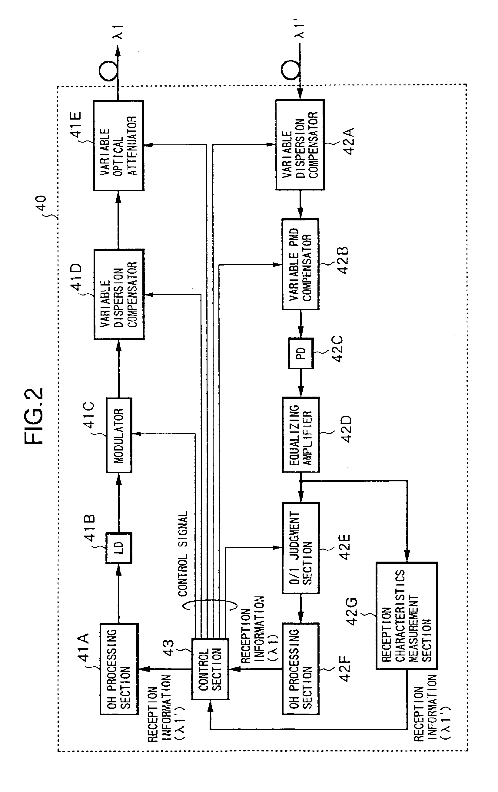
[0013]With such a construction, pre-emphasis is performed by the pre-emphasis performing means, and WDM signal light that has been applied with an optical wavelengthchirp by the chirp applying means is transmitted through the optical transmission path from the transmitting terminal station to the receiving terminal station. At the receiving terminal station, the WDM signal light transmitted is received and processed, and also the reception information about each wavelength is measured by the reception characteristics measurement means. The reception information about each wavelength is information containing an optical signal to noise ratio (OSNR) and a transmission error rate represented by a bit error rate or a value Q, which is transmitted back to the transmitting terminal station end by the reception information transmission means. At the transmitting terminal station, depending on the reception information about each wavelength from the receiving end, the setting of pre-emphasis and the setting of the parameter a representing the intensity of the optical wavelengthchirp are feedback controlled by the control means. As a result, optimal transmission conditions can be obtained, and hence it is possible to compensate reliably for deviation of transmission characteristics of the optical signals of respective wavelengths including degradation by an influence of nonlinear optical effects.
[0015]By using a reception characteristics measurement means with such a construction, it is possible to measure the reception information about each wavelength with a simply constructed electric circuit without using a light spectrum analyzer.
[0017]With such a construction, WDM signal light on which pre-emphasis is performed by the pre-emphasis performing means is transmitted from the transmitting terminal station along the optical transmission path, and repeatedly transmitted to the receiving terminal station, while being amplified by the optical amplification means in the optical repeater station arranged along the optical transmission path. At the receiving terminal station, the transmitted WDM signal light is received and processed, and also the reception information containing OSNR and transmission error rate of the optical signals of respective wavelength is measured by the reception characteristics measurement means, to be transmitted to the transmitting terminal station end by the reception information transmission means. At the transmitting terminal station, depending on the reception information about each wavelength from the receiving end, the setting of pre-emphasis is feedback controlled by the control means, and also the reception information about each wavelength is transferred to the optical repeater station by the reception information transfer means. At the optical repeater station, a supply condition of Raman excitation light is feedback controlled by the Raman amplification control means. In this manner, optimal transmission conditions are realized, thus enabling reliable compensation of the deviation of transmission characteristics.
Problems solved by technology
However, due to the abovementioned deviation of transmission characteristics, the OSNR of an optical signal of a specific wavelength is worse in a wavelength division multiplexed optical signal, so that, in spite of there being an optical signal of a wavelength with a good OSNR, the transmission characteristics are estimated by the worst OSNR.
Furthermore, another main cause of deviation of transmission characteristics is known in that, for example, in a WDM optical communication system including optical add drop nodes, variation of the OSNR occurs at the receiving end due to a difference in the number of optical amplifiers that each channel passes through.
However, in a conventional WDM optical communication system wherein pre-emphasis is performed as mentioned above, there is a problem in that, if the pre-emphasis amount to be applied to the WDM signal light increases, the influence of nonlinear optical effects increases, so that the transmission characteristics are degraded.
Such degradation due to the influence of nonlinear optical effects is difficult to determine accurately by monitoring only the OSNR conditions at the receiving end.
Therefore, there is a case where optimal transmission characteristics cannot be obtained, even though pre-emphasis is controlled depending on the OSNR monitored at the receiving end in a conventional manner.
Furthermore, there is another problem in conventional WDM optical communication systems in that, if the range of waveband of WDM signal light is expanded, deviation of the transmission characteristics is difficult to limit sufficiently by only the pre-emphasis control performed at the transmitting end.
However, there has been a case in that, if pre-emphasis of an optical signal with such a broad waveband is to be controlled only at the transmitting end, a required amount of pre-emphasis control becomes difficult to be performed owing to the control range constraints of variable optical attenuators and the like that control the power of transmitted light.
Method used
Image
Click on the blue label to locate the original text in one second.
Reading with bidirectional positioning of images and text.
Examples
first embodiment
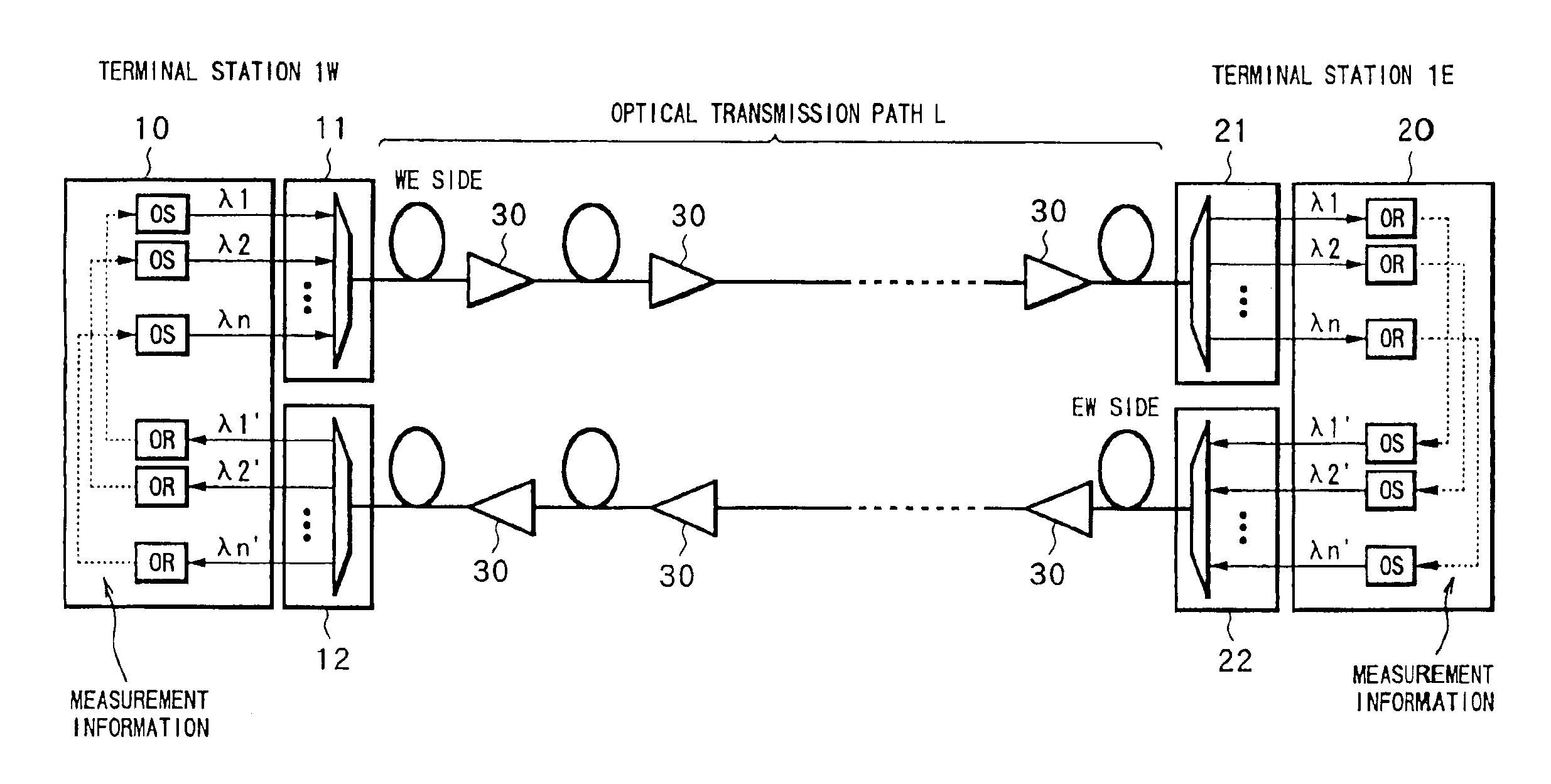
[0037]FIG. 1 shows a structure of a WDM optical communication system according to a
[0038]In FIG. 1, the construction of the present WDM optical communication system is, for example, that two transmitting-receiving terminal stations, 1W and 1E, are connected by an optical transmission path L comprising two lines of opposing transmission directions. Here, the line that transmits WDM signal light from the terminal station 1W to the terminal station 1E is designated the WE line, and the line that transmits from the terminal station 1E to the terminal station 1W is designated the EW line. In both the WE line and the EW line, a plurality of optical amplifiers (optical repeaters) 30 are arranged at required repeater spacing. A system constructed like this is suitable for a land WDM optical communication system.
[0039]The terminal station 1W, for example, has a transmitter-receiver 10 and WDM apparatuses 11 and 12. The transmitter-receiver 10 transmits respective optical signals of wavelengt...
second embodiment
[0078]Next is a description of a
[0079]In the first embodiment mentioned above, the construction is such that the reception information of the OSNR and BER obtained at the receiving end is superimposed on the overhead information of the optical signal transmitted on the opposing line, and forwarded to the transmitting end. However in the second embodiment, a case is considered where the reception information of the OSNR and BER is transmitted on an optical supervisory channel (OSC), so that the operating conditions of the WDM apparatus inside the station, the optical amplifiers arranged on the optical transmission path L, and the like can be controlled depending on the OSNR and BER.
[0080]FIG. 5 shows the structure of a WDM optical communication system according to the second embodiment. Here, the same symbols are used for the same structures as in the first embodiment, and this is the same hereunder.
[0081]In FIG. 5, the point of difference in the structure of the present WDM optical ...
third embodiment
[0101]Next is a description of the present invention.
[0102]FIG. 10 shows a structure of a WDM optical communication system according to the third embodiment.
[0103]In FIG. 10, the construction of the present WDM optical communication system is, similarly to the case in the first embodiment, for example that the two transmitter-receiver terminal stations, 100W and 100E, are connected by an optical transmission path L comprising two lines (WE side and EW side) of opposing transmission directions. In each line, a plurality of optical repeaters 130 is arranged at required repeater spacing. A system constructed as described hereunder is suitable, for example for a seabed WDM optical communication system.
[0104]The terminal station 100W has, for example, an optical transmitting section 101S and an optical receiving section 101R. The WDM signal light of wavelengths λ1˜λn, which is generated in the optical transmitting section 101S, is transmitted to the WE line of the optical transmission pa...
PUM
Abstract
The object of the present invention is to provide a WDM optical communicationsystem and a WDM communication method wherein deviation of transmission characteristics of optical signals of respective wavelengths is reliably controlled, based on reception information such as the OSNR, BER and the like measured at the receiving end, thereby enabling optimal transmission conditions to be realized. For this purpose, the present WDM optical communicationsystem transmits WDM signal light of wavelengths λ1˜λn, which has been generated by the transmitting end of one terminal station, to the receiving end of the other terminal station through an optical transmission path. At the receiving end, the OSNR and BER of the optical signals of wavelengths λ1˜λn are measured, and the result is superimposed on overhead information transmitted along the opposing line of the optical transmission path as reception information. At the transmitting end, the settings of pre-emphasis and a parameter α are feedback controlled based on the reception information about each wavelength transmitted, and deviation of transmission characteristics of respective wavelengths is thus suppressed.
Description
BACKGROUND OF THE INVENTION[0001]1. Field of the Invention[0002]The present invention relates to a wavelength division multiplexing (WDM:Wavelength Division Multiplexing) optical communication technique. In particular, the present invention relates to a WDM optical communication system and a WDM optical communication method, wherein pre-emphasis is performed on optical signals of respective wavelengths depending on reception information measured at the receiving end.[0003]2. Description of Related Art[0004]In recent years, research and development of WDM optical communication systems have been carried on actively with an aim toward a large transmission capacity of communication lines. With conventional WDM optical communication systems, it is known that deviation of transmission characteristics occurs in optical signals of respective wavelengths. The transmission characteristics of a WDM optical communication system can be measured, for example, by the SN ratio of the optical signal...
Claims
Application Information
Patent Timeline
Application Date:The date an application was filed.
Publication Date:The date a patent or application was officially published.
First Publication Date:The earliest publication date of a patent with the same application number.
Issue Date:Publication date of the patent grant document.
PCT Entry Date:The Entry date of PCT National Phase.
Estimated Expiry Date:The statutory expiry date of a patent right according to the Patent Law, and it is the longest term of protection that the patent right can achieve without the termination of the patent right due to other reasons(Term extension factor has been taken into account ).
Invalid Date:Actual expiry date is based on effective date or publication date of legal transaction data of invalid patent.

