Apparatus and method for precise lapping of recessed and protruding elements in a workpiece

Inactive Publication Date: 2005-08-30
HITACHI GLOBAL STORAGE TECH NETHERLANDS BV
View PDF8 Cites 40 Cited by
  • Summary
  • Abstract
  • Description
  • Claims
  • Application Information

AI Technical Summary

Benefits of technology

[0012]The present invention provides a lapping method utilizing textured and conditioned lapping plates which are most suitable for finishing magnetic heads resulting in improved surface quality less sensitivity to electrical shorts due to smears and reduced surface height difference (recession) between the head elements exposed at the slider air bearing surface. The lapping process can proceed in a succession of steps or phases in which a rough lapping phase using a diamond slurry is followed by a second phase or polishing phase that maintains the same mechanical motion between the work piece and lapping plate but utilizes only the lapping plate without abrasives of any kind to polish the work piece surface, and to clean up any deep textured mark

Problems solved by technology

These electrically active components during lapping can scratch and smear into the other components causing electrical shorts and degraded head performance.
As a result, poor head performance because of increase space in between the critical elements and the recording disc can occur.
One of several problems experienced is that the surface is susceptible to rapid change in smoothness as it is used to lap a workpiece during lapping.
A change in smoothness effects the hydrodynamic bearing film provided by the liquid component of the abrasive slurry creating a hydroplaning effect which raises the workpiece from the lapping surface to diminish the abrasion action

Method used


Image

  • Apparatus and method for precise lapping of recessed and protruding elements in a workpiece
  • Apparatus and method for precise lapping of recessed and protruding elements in a workpiece
  • Apparatus and method for precise lapping of recessed and protruding elements in a workpiece

Examples


Embodiment Construction

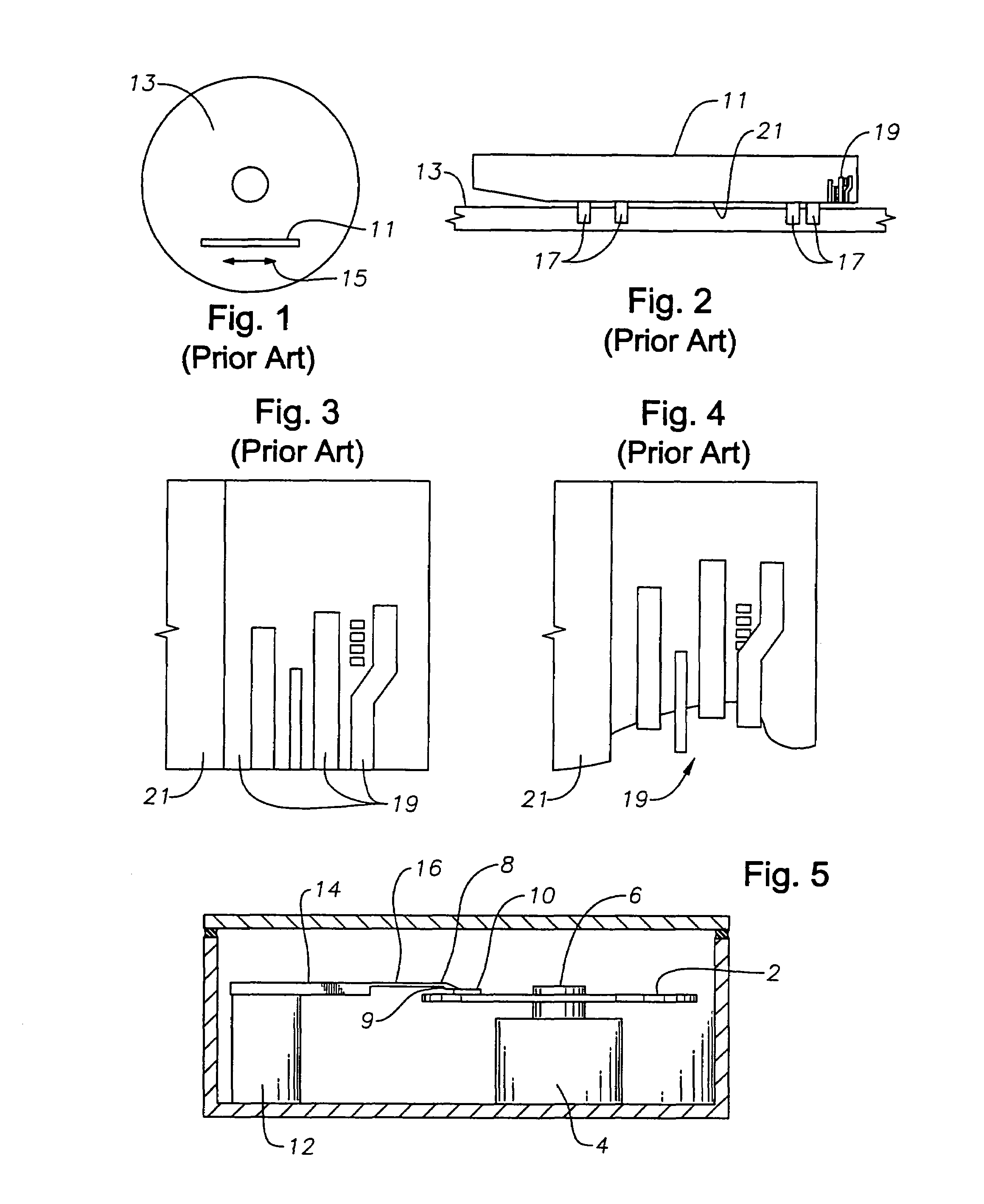
[0027]Referring to FIGS. 5 and 6, there is shown a magnetic recording disc drive, and a magnetic recording disc 2 rotated by drive motor 4 with a hub 6 which is attached to the drive motor 4. The recording disc 2 comprises a substrate, a metallic magnetic layer, a carbon layer and a polymeric lubricant layer such as perfluoropolyether.

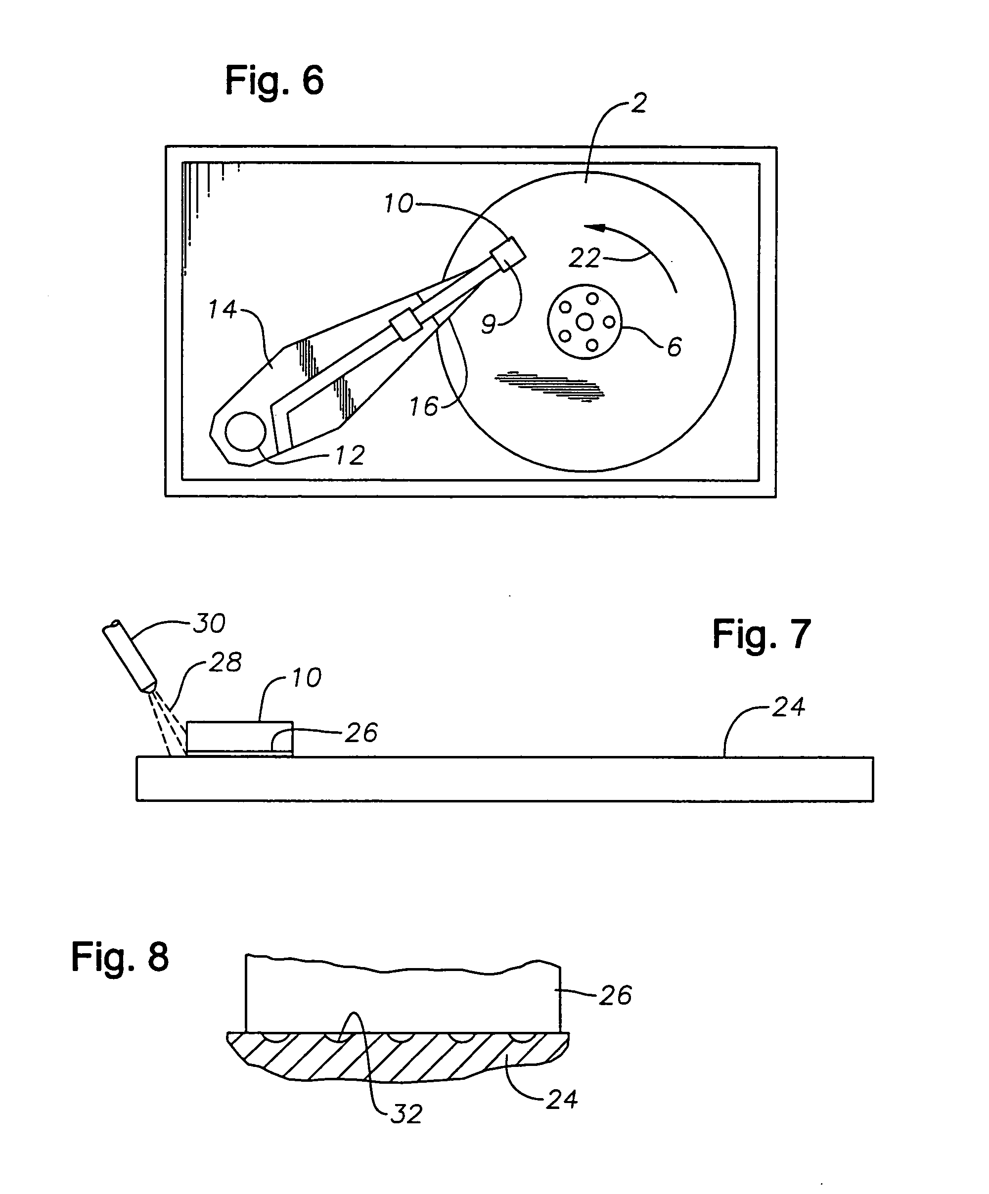
[0028]A read / write head or transducer 8 is formed on the trailing end of a carrier, or slider 10. Head 8 may be an inductive read and write transducer, and sliders may be positive or negative air bearing sliders. The slider 10 has a trailing surface 9 and is connected to an actuator 12 by means of a rigid arm 14 and a suspension element 16. The suspension element 16 provides a bias force which urges the slider 10 toward the surface of the recording disc 2. During operation of the disc drive, the drive motor 4 rotates the recording disc 2 at a constant speed in the direction of arrow 22. The actuator 12, which is typically a linear or rotary motion coil...


PUM

PropertyMeasurementUnit
Fractionaaaaaaaaaa
Mechanical propertiesaaaaaaaaaa
Surfaceaaaaaaaaaa

Abstract

A lapping method utilizing textured and conditioned lapping plates most suitable for finishing magnetic heads resulting in improved surface quality, less sensitivity to electrical shorts due to smears, and reduced surface height difference between the head elements exposed at the slider air bearing surface. A rough lapping phase is followed by a polishing phase that maintains the same mechanical motion between the work piece and lapping plate but utilizes only the lapping plate without abrasives of any kind to polish the work piece surface, and to clean up any deep textured marks resulting from the diamond slurry phase. A conductive liquid is utilized to provide lubrication and to minimize static charge.

Description

BACKGROUND OF THE INVENTION[0001]1. Technical Field[0002]The present invention relates in general to lapping workpieces, and in particular to improving the precision of a lapping process for magnetic transducers. Still more particularly, the present invention relates to a precisely controlling lapping of a workpiece having an element that is recessed in or protruding from the lapped surface of the air bearing surfaces of magnetic transducers.[0003]2. Description of the Prior Art[0004]Magnetic recording is employed for large memory capacity requirements in high speed data processing systems. For example, in magnetic disc drive systems, data is read from and written to magnetic recording media utilizing magnetic transducers commonly referred to as magnetic heads. Typically, one or more magnetic recording discs are mounted on a spindle such that the disc can rotate to permit the magnetic head mounted on a moveable arm in position closely adjacent to the disc surface to read or write in...

Claims


Application Information

Patent Timeline
IPC IPC(8): G11B5/127G11B5/147H04R31/00B24B37/04
CPCB24B37/042B24B37/16Y10T29/49052Y10T29/49046Y10T29/49048Y10T29/49043Y10T29/49044Y10T29/49041Y10T29/53165Y10T29/5313
Inventor MARKEVITCH, YURIMCMASTER, MARK C.CHANG, YU-EN PERCY
Owner HITACHI GLOBAL STORAGE TECH NETHERLANDS BV
Why Eureka
Try Eureka