
Hybrid type sensor for detecting high frequency partial discharge

Inactive Publication Date: 2005-08-30
HANYANG HAK WON CO LTD
View PDF15 Cites 43 Cited by
  • Summary
  • Abstract
  • Description
  • Claims
  • Application Information

AI Technical Summary

Benefits of technology

[0011]Accordingly, the present invention has been made keeping in mind the above problems occurring in the prior art. The present invention overcomes these problems by providing a hybrid type sensor for detecting high frequency partial discharge, which is not influenced by power noise and surrounding noise, and is capable of safely detecting the amounts of high frequency partial discharge ranging from a few mV to several hundred mV at a high signal-to-noise ratio even though a high surge voltage is input to the sensor due to breakdown.
[0016]The hybrid type sensor may further comprise a dummy inductor disposed between the first and second impedance forming units and the second measurement terminal, thus reducing ground noise.
[0022]The hybrid type sensor may further comprise a dummy inductor disposed between the first and second impedance forming units and the second measurement terminal, thus reducing ground noise.

Problems solved by technology

However, since the level of a partial discharge signal is as low as a few mV to several hundred mV, external noise may be easily input to the power equipment.
Therefore, the HFPD detecting scheme is problematic in that it is difficult to measure a partial discharge current due to the limitation of the capacitance of the coupling capacitor, and, additionally, a large-sized inspecting device and many investment costs are required.
The shunt type sensor has the most ideal precision, but it is disadvantageous in that, when breakdown occurs, a high surge voltage may be induced at an input terminal of the sensor to damage a test system and power noise may be input to the sensor.
However, actually, self-resonance occurs at higher frequencies due to stray capacitance or inductance caused by a lead wire, so that impedance is increased at higher frequencies.
Therefore, it is difficult to measure partial discharge in high frequency bands.
As described above, since the conventional high frequency partial discharge detecting sensors have many problems, it is difficult to apply the sensors to actual inspection fields.

Method used


Image

  • Hybrid type sensor for detecting high frequency partial discharge
  • Hybrid type sensor for detecting high frequency partial discharge
  • Hybrid type sensor for detecting high frequency partial discharge

Examples


first embodiment

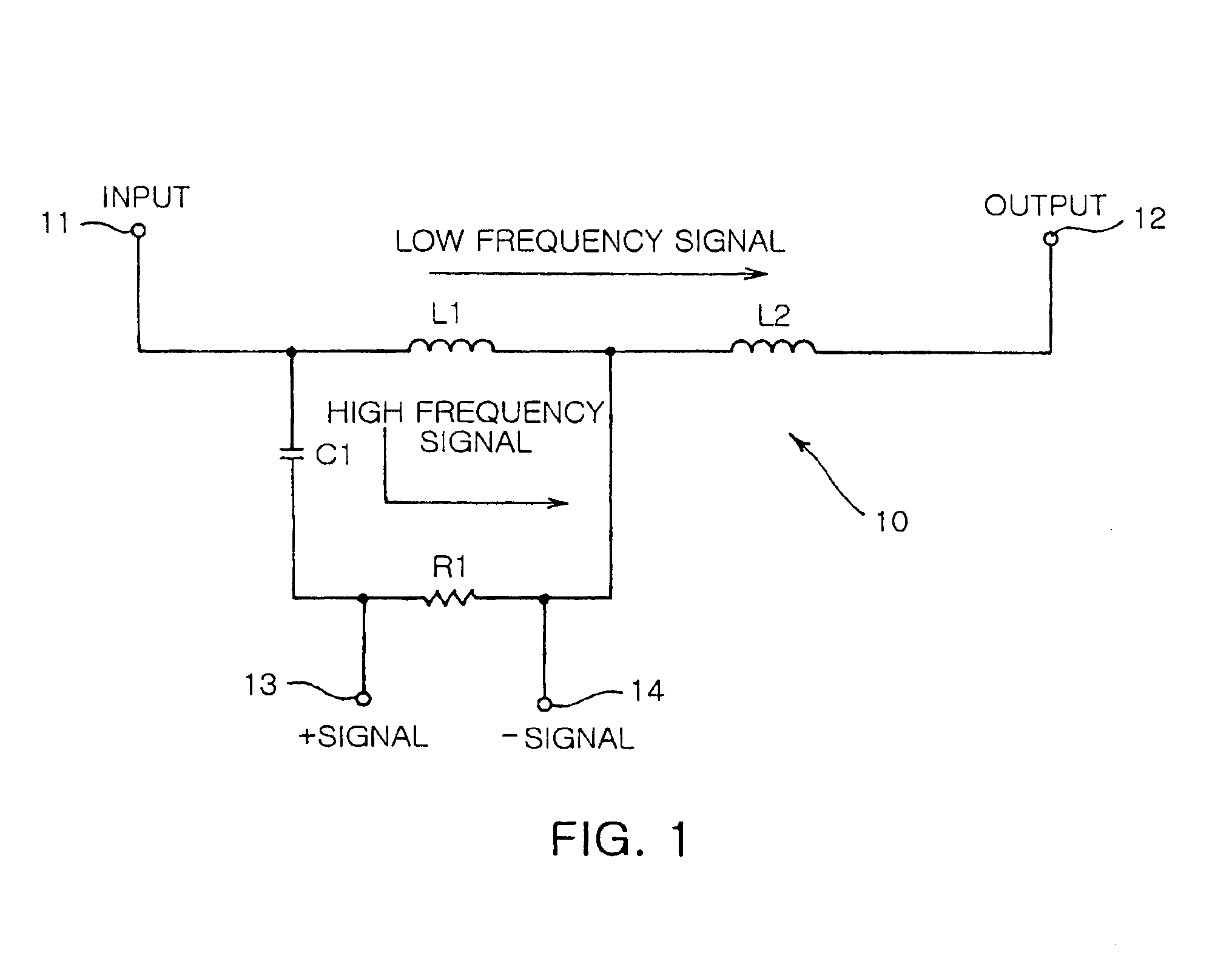
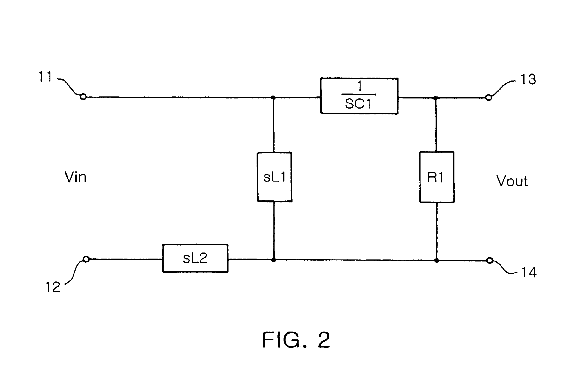
[0048]FIG. 1 is a circuit diagram of a hybrid type sensor for detecting high frequency partial discharge according to the present invention. As shown in FIG. 1, a sensor 10 includes a first measurement terminal 11 connected to a power device, which is an inspection object, to receive power signals, a second measurement terminal 12 connected to ground, a first inductor L1 disposed between the first and second measurement terminals 11 and 12 so as to allow a low frequency power signal of the power signals, input to the first measurement terminal 11, to flow to the second measurement terminal 12, a capacitor C1 disposed between the first and second measurement terminals 11 and 12 so as to allow a high frequency fine partial discharge signal of the power signals, input to the first measurement terminal 11, to pass through the capacitor C1, a resistor R1 connected in series to the capacitor C1 to determine a resonance point by the coupling of the capacitor C1 and the first inductor L1, a...

second embodiment

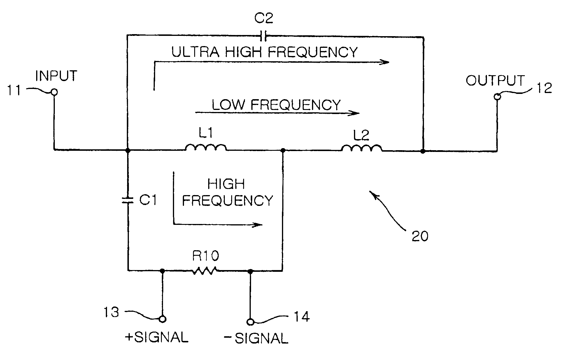
[0051]Next, FIG. 3 is a circuit diagram of a hybrid type high frequency partial discharge detecting sensor according to the present invention. As shown in FIG. 3, a sensor 20 includes a first measurement terminal 11 connected to a power device, which is an inspection object, to receive power signals, a second measurement terminal 12 connected to ground, a first inductor L1 disposed between the first and second measurement terminals 11 and 12 so as to allow a low frequency power signal of the power signals, input to the first measurement terminal 11, to flow to the second measurement terminal 12, a first capacitor C1 disposed between the first and second measurement terminals 11 and 12 so as to allow a high frequency fine partial discharge signal of the power signals, input to the first measurement terminal 11, to pass through the first capacitor C1, a resistor R1 connected in series to the first capacitor C1 to determine a resonance point by the coupling of the first capacitor C1 an...

experiment 1

[0081

[0082]An experiment for measuring discharge in air performed in parallel-plate electrodes using the hybrid type sensor of the present invention was carried out. The experiment was carried out in such a way that a sensor 122 of the present invention is installed at a ground side of parallel-plate electrodes 121, which are inspection objects, to be perpendicular to a current direction as shown in FIG. 12. Further, in order to objectively compare the performance of the sensor of the present invention with that of another sensor, results measured by both the sensor of the present invention and a general CT type sensor with respect to an equal measurement object are compared with each other. The general CT type sensor is commercialized by Power Diagnostics (PD) Corporation and recognized as international high frequency partial discharge measuring equipment. In the experiment, a frequency band for the partial discharge measurement is 1 MHz to 100 MHz. The CT type sensor of the PD Cor...


PUM


Abstract

Disclosed herein is a hybrid type sensor for detecting high frequency partial discharge which can detect high frequency partial discharge at a high signal-to-noise ratio without being influenced by power noise and surrounding noise, and guarantee the safety of a test when breakdown occurs. The sensor forms two or three signal paths with different impedances wherein a low frequency power signal is bypassed to ground through a first path, and a high frequency partial discharge current is allowed to flow through a second path and is detected as a resistance component through a resistor. Further, a surge voltage input to the sensor due to breakdown is input to the ground through a third path.

Description

BACKGROUND OF THE INVENTION[0001]1. Field of the Invention[0002]The present invention relates, in general, to a sensor for detecting the amount of partial discharge required to inspect insulated conditions of power devices and, more particularly, to a hybrid type sensor for detecting high frequency partial discharge, which is not influenced by power noise and surrounding noise, and is capable of safely detecting the amounts of high frequency partial discharge ranging from a few mV to several hundred mV at a high signal-to-noise ratio even though a high surge voltage is input to the sensor due to breakdown.[0003]2. Description of the Related Art[0004]Generally, an inspection for insulated conditions of power equipment is performed by analyzing partial discharge radiated from the power equipment. However, since the level of a partial discharge signal is as low as a few mV to several hundred mV, external noise may be easily input to the power equipment. Therefore, there have progressed...

Claims


Application Information

Patent Timeline
IPC IPC(8): G01R31/12
CPCG01R31/1272
Inventor KOO, JA YOONKIM, JEE HONG
Owner HANYANG HAK WON CO LTD
Learn More