Resistor tuning network and method for tuning a resistor in an electronic circuit

a technology of resistor and tuning network, which is applied in the direction of digital-analog convertors, transmission systems, instruments, etc., can solve the problems of component parameter dependence, analog processing accuracy, and component value variation in one fabrication run, so as to achieve good linearity in the tuning transfer function, large spread of resistor values, and high tuning accuracy

Inactive Publication Date: 2005-08-30
NAT SEMICON CORP
View PDF19 Cites 17 Cited by
  • Summary
  • Abstract
  • Description
  • Claims
  • Application Information

AI Technical Summary

Benefits of technology

[0021]In one advantageous embodiment of the present invention, the resistor tuning network is integrated on a microchip on which an RC filter is built. In another advantageous embodiment of the present invention, the R-xR ladder network is an R-2R ladder network. By connecting a resistance in parallel with an R-2R ladder network, a resistor tuning network is provided that has good linearity in its tuning transfer function and allows a large spread of resistor values. With this arrangement, high tuning accuracy is achieved with a small spread in resistor values. Because the switches in the R-2R ladder are all in series with the same amount of resistance (i.e., 2R), they can be uniformly sized. By selecting 2R to be of the order of one thousand ohms (1 kilohm) or more, switch sizes can be made small, enabling the network to be integrated into a microelectronic chip or silicon chip.

Problems solved by technology

While microchip processing is extremely efficient in building a large number of devices on a microchip, analog processing still suffers from variations in component values from one fabrication run to another.
Further limitations to analog processing accuracy come from the dependence of component parameters on temperature, which is becoming more and more costly to control as a result of larger scale integration.
As the dominant non-ideality of a reasonably-sized micro-switch is its parasitic resistance (up to very high frequencies), tuning of capacitors poses a difficulty as a result of an undesired resistance appearing in series with the capacitor to be tuned.
This necessarily requires large size switches, such that the parasitic switch resistance can be neglected next to the tuning resistors.
Note that, increased switch size, besides requiring more chip real estate, also exhibits higher parasitic capacitance along the signal path, and increased noise coupling through the substrate.
The large spread of resistor values also limits the accuracy and matching between resistors.
Small-valued resistors also require much more hand-tailoring in layout, as their aspect ratios turn out to be awkward, and parasitic contact resistances introduce considerable error to the overall resistance.
Another difficulty is that different tuning resistor values are needed for each different resistor value to be tuned (so that the same relative accuracy can be maintained across all resistors).

Method used


Image

  • Resistor tuning network and method for tuning a resistor in an electronic circuit
  • Resistor tuning network and method for tuning a resistor in an electronic circuit
  • Resistor tuning network and method for tuning a resistor in an electronic circuit

Examples


example one

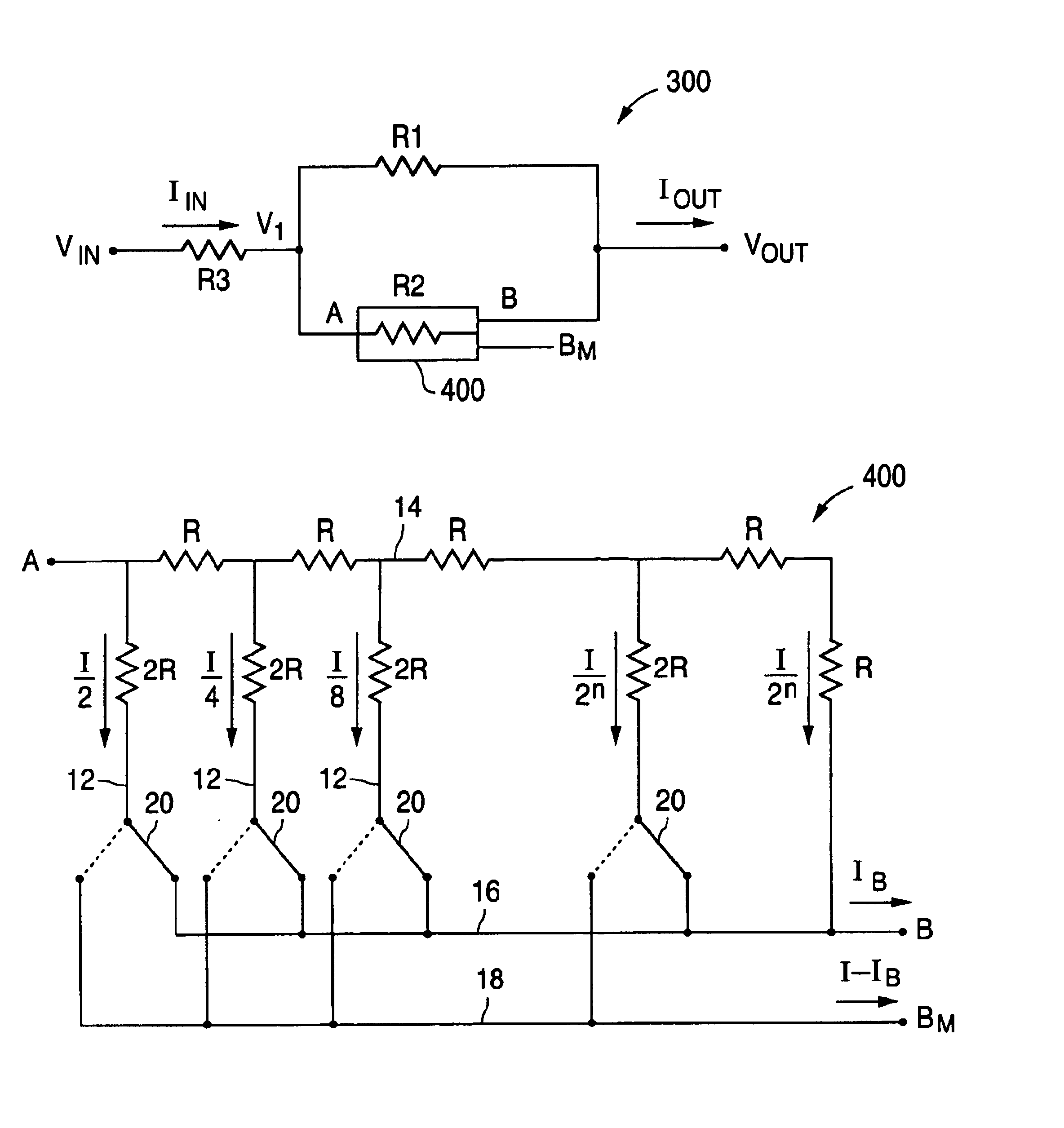
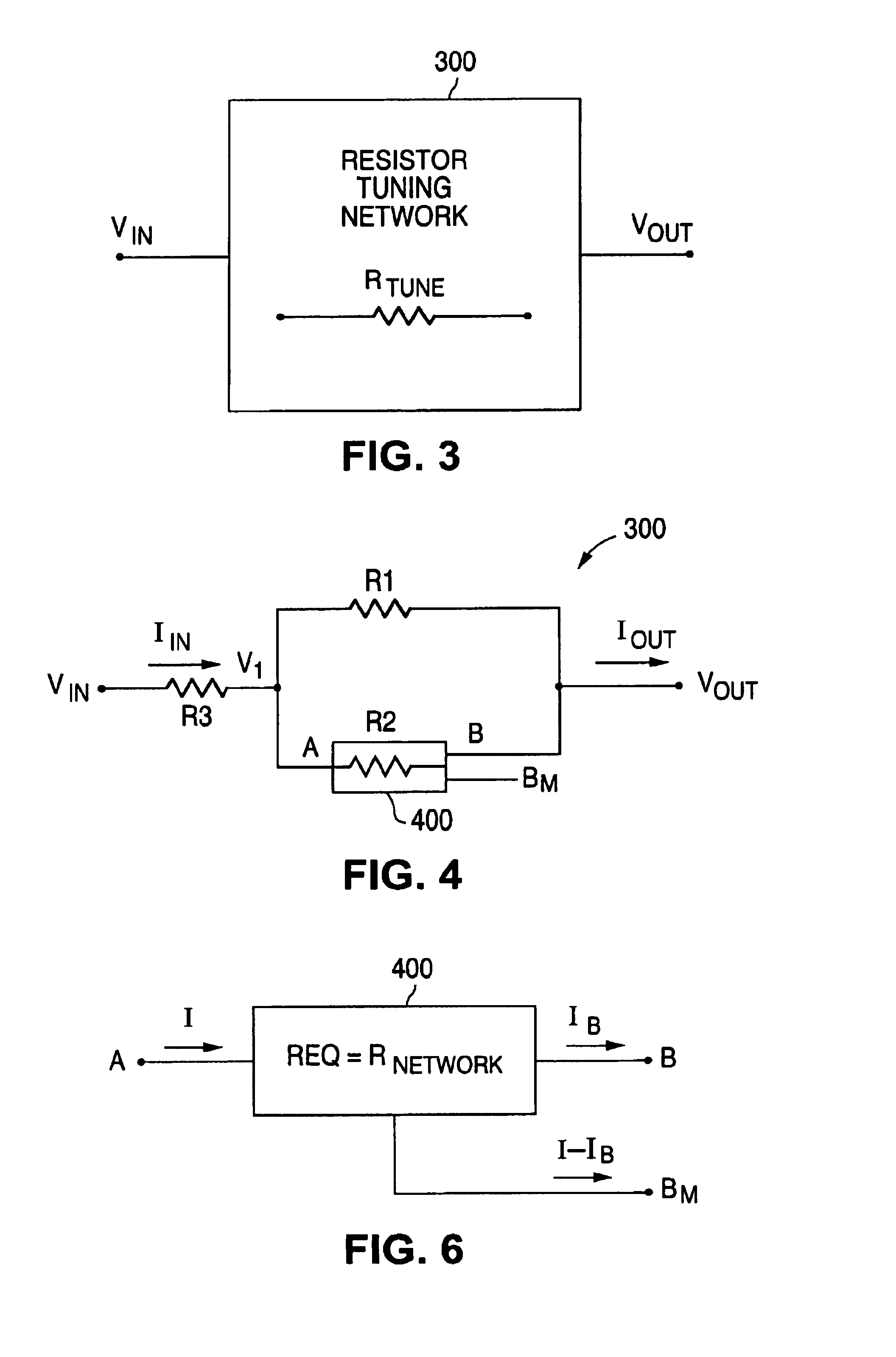
[0048]FIG. 7 illustrates a first example of tuning of an equivalent resistor value (REQ) variation of resistor tuning network 300 of the present invention. Assume that a resistor RTUNE needs to be provided that has resistor values tuned to values within five percent (5%) of a five thousand ohm resistor (5.0 kilohms) over an expected process variation of plus or minus forty percent (±40%). The value of resistor R1 is chosen to be ten thousand ohms (10.0 kilohms) and the value of resistor R2 is chosen to be five thousand ohms (5.0 kilohms). The value of series resistor R3 is chosen to be zero ohms (0.0 ohms).

[0049]The value of resistor R2 is chosen to be a four (4) bit R-2R ladder network. That is, the value “n” in the R-2R ladder network is chosen to be four (4). In the case of a five thousand ohm resistor (5.0 kilohms), a binary setting of “1000” for the four switches in the R-2R ladder network provides an equivalent resistance of five thousand ohms (5.0 kilohms). A binary setting o...

example two

[0054]FIG. 8 illustrates a second example of tuning of an equivalent resistor value (REQ) variation of resistor tuning network 300 of the present invention. Assume that a resistor RTUNE needs to be provided that has resistor values tuned to values within five percent (5%) of an eight thousand ohm resistor (8.0 kilohms) over an expected process variation of plus or minus forty percent (±40%). The value of resistor R1 is chosen to be ten thousand ohms (10.0 kilohms) and the value of resistor R2 is chosen to be five thousand ohms (5.0 kilohms). The value of series resistor R3 is chosen to be two thousand ohms (2.0 kilohms).

[0055]The value of resistor R2 is chosen to be a four (4) bit R-2R ladder network. That is, the value “n” in the R-2R ladder network is chosen to be four (4). In the case of an eight thousand ohm resistor (8.0 kilohms), a binary setting of “1000” for the four switches in the R-2R ladder network provides an equivalent resistance of eight thousand ohms (8.0 kilohms). A...


PUM


Abstract

A resistor tuning network is disclosed that comprises a first resistor connected in parallel with a second variable resistor and a third resistor coupled in series with the first resistor and the second variable resistor. The second variable resistor comprises an R-2R ladder network having an input and first and second output terminals, with a first line having a plurality of first arms connected in series with the input and first output terminal and nodes between each pair of arms, each arm having an identical resistor R. A series of shunt arms, each with a 2R resistor and a switch, are selectively connected between the respective nodes and the first or second output terminal. The resistance of the resistor tuning network is tuned by varying the switch positions in the shunt arms in the R-2R ladder network.

Description

CROSS-REFERENCE TO RELATED APPLICATIONS[0001]This patent application is related to and claims priority as a continuation-in-part of U.S. patent application Ser. No. 09 / 778,540 filed on Feb. 7, 2001 which is now U.S. Pat. No 6,573,811 for “RESISTOR TUNING NETWORK AND METHOD FOR MICROELECTRONIC RC-BASED FILTERS.”[0002]The present invention is also related to that disclosed in U.S. patent application Ser. No. 09 / 934,158 filed Aug. 21, 2001, entitled “EFFICIENT IMPLEMENTATION OP A COMPLEX FILTER WITH ON-CHIP RESISTOR TUNING;”[0003]The above applications are commonly assigned to the assignee of the present invention. The disclosures of these related patent applications are hereby incorporated by reference for all purposes as it fully set forth herein.TECHNICAL FIELD OF THE INVENTION[0004]The present invention relates generally to the tuning of a resistor in an electronic circuit, and, in particular, to the tuning of a resistor in an on-chip, microelectronic component such as an RC filter...

Claims


Application Information

Patent Timeline
Patent Type & Authority Patents(United States)
IPC IPC(8): H03H1/00H03H1/02H03H7/01H03H7/25H03H7/12H03H7/24
CPCH03H7/25
Inventor MARTIN, BRIAN C.
Owner NAT SEMICON CORP
Why Eureka
Try Eureka