Hydraulic forming process, hydraulic forming device and metal separator for a fuel cell formed by hydraulic forming process

a technology of hydraulic forming and hydraulic forming process, which is applied in the direction of cell components, final product manufacturing, sustainable manufacturing/processing, etc., can solve the problems of complicated and expensive overall construction of hydraulic forming devices, and achieve high precision, increased fluid pressure, and sufficient joint area

Inactive Publication Date: 2005-09-06
TOYOTA SHATAI KK
View PDF15 Cites 29 Cited by
  • Summary
  • Abstract
  • Description
  • Claims
  • Application Information

AI Technical Summary

Benefits of technology

[0027]According to these, the metal separator for a fuel cell formed by the aforesaid hydraulic forming process has the convex sections transferred with high precision by the formed section of the upper die and the fluid having the increased fluid pressure. Therefore, in case where the metal separator are laminated with each other to form a fuel cell stack, a sufficient joint area can be assured to thereby enhance conductivity between the metal separators. Moreover, the distortion caused upon forming the convex sections can be eliminated, thereby being capable of improving assembility upon assembling the metal separators.
[0028]Further, the fuel cell stack is required to be composed by multi-layering the metal separators since electricity of larger capacity is generated, whereby a si

Problems solved by technology

However, the conventional hydraulic forming process requires to increase the fluid pressure by the pressure pump upon preforming the thin metal plate.
Therefore, t

Method used


Image

  • Hydraulic forming process, hydraulic forming device and metal separator for a fuel cell formed by hydraulic forming process
  • Hydraulic forming process, hydraulic forming device and metal separator for a fuel cell formed by hydraulic forming process
  • Hydraulic forming process, hydraulic forming device and metal separator for a fuel cell formed by hydraulic forming process

Examples


first embodiment

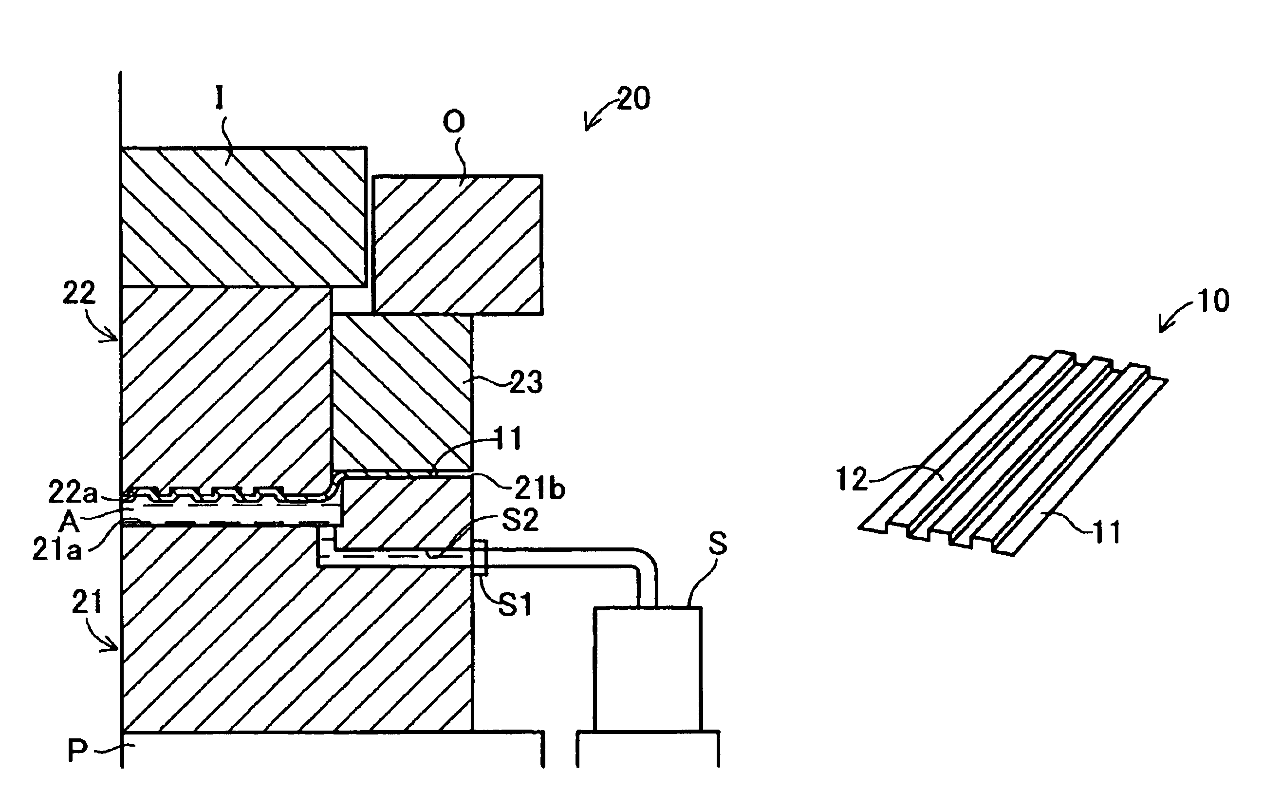
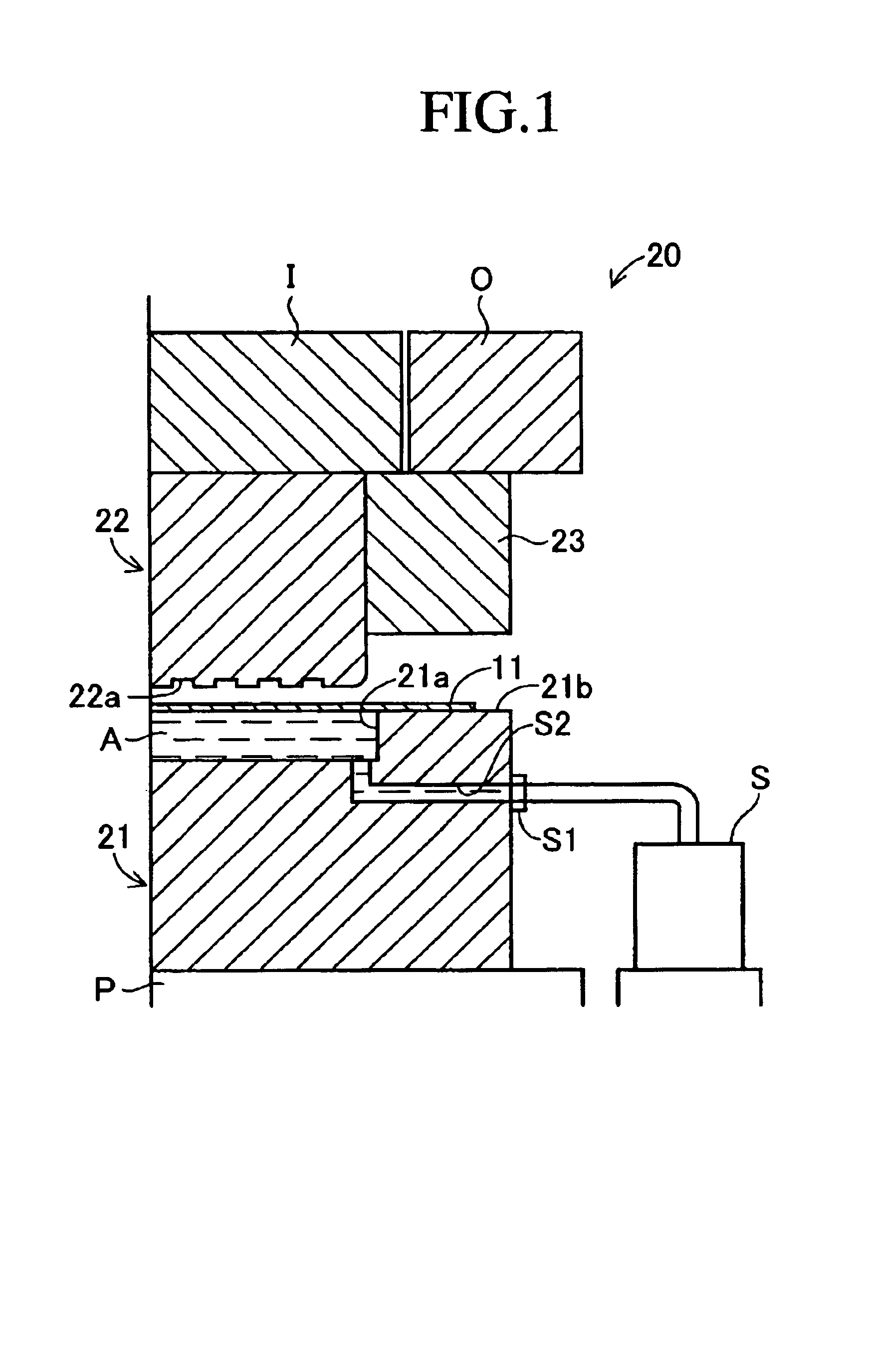
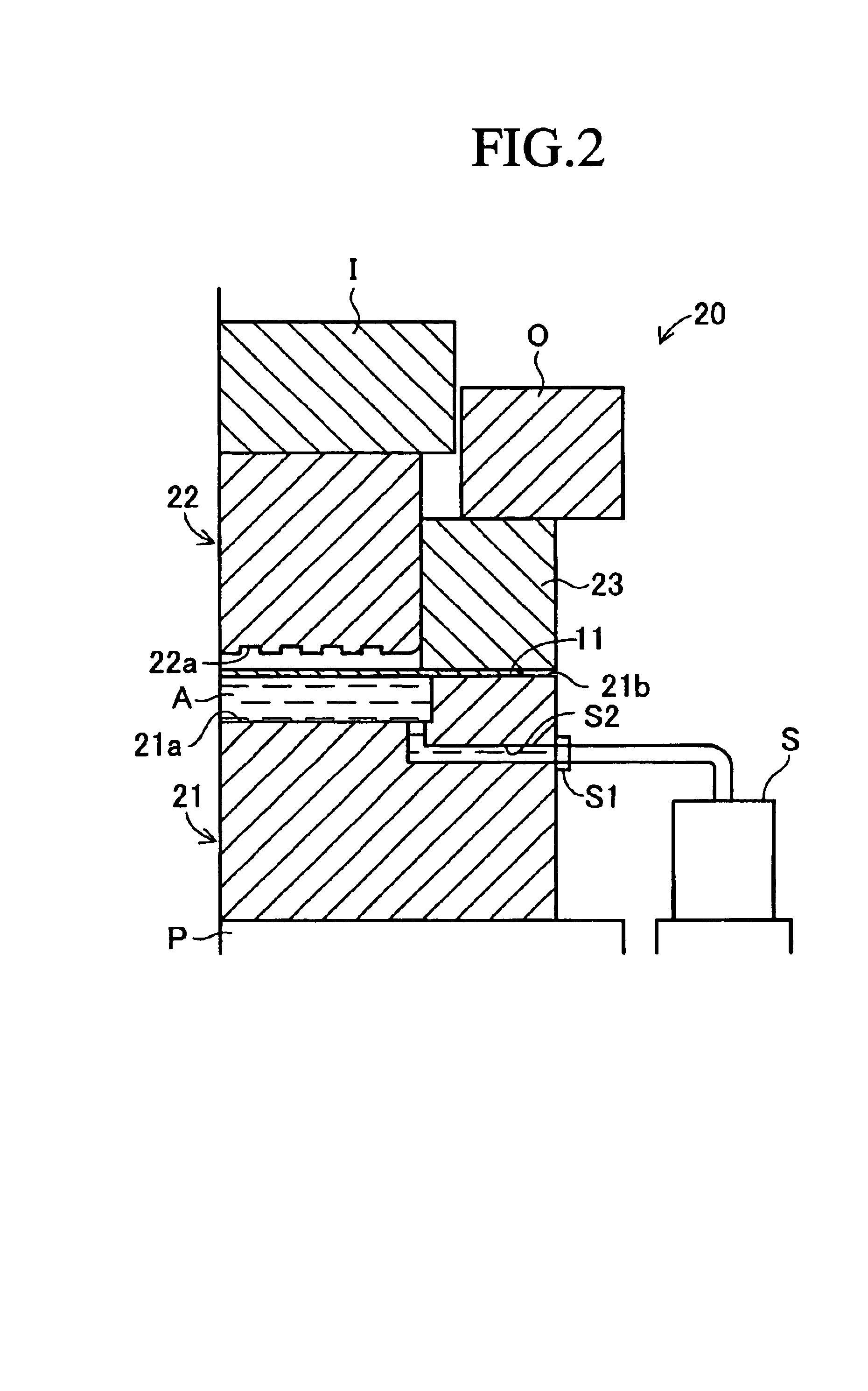
[0042]the present invention will be explained hereinbelow with reference to the drawings. FIG. 1 to FIG. 4 show each process according to one embodiment of the present invention for fabricating a thin metal plate having a plurality of rib-like convex sections on its surface, in particular a metal separator for a fuel cell. A hydraulic forming device 20 successively proceeds with each process to fabricate a metal separator 10 composing a fuel cell stack as schematically shown in FIG. 5A in which an essential part is enlarged.

[0043]Fabricated two metal separators 10 are joined together at one side with a membrane-electrode assembly (MEA) composed of an anode electrode AE, electrolyte film EF and cathode electrode CE interposed therebetween, to thereby form a fuel cell stack. Two separators 10 are joined at one side via the MEA as described above, resulting in forming a hydrogen gas channel HC through which hydrogen is supplied and an oxygen gas channel OC through which oxygen gas (for...

second embodiment

[0089]In this second embodiment, the pressure sensor PS can be mounted to the sensor-mounted port 36, so that, when the pressure sensor PS is mounted, the detected value outputted from the sensor PS can be displayed on a display device of a personal computer not shown as the fluid pressure in the hollow section 21a. An operator who monitors the operation state of the hydraulic forming device 20 can confirm whether the fluid pressure in the hollow section 21a rises to the predetermined pressure or not by this display, which means that he / she can confirm whether the metal separator 10 is formed under a predetermined forming condition or not.

[0090]Therefore, whether the forming state of a product is good or not can be checked based upon the fluid pressure of the hydraulic fluid A outputted from the pressure sensor PS, thereby being capable of keeping the quality of the product satisfactory. Further, the operation amount of the hydraulic forming device 20, i.e., the operation amount of ...


PUM

PropertyMeasurementUnit
Specific surface areaaaaaaaaaaa
Kinematic viscosityaaaaaaaaaa
Pressureaaaaaaaaaa

Abstract

By using a hydraulic forming device 20, a metal plate body 11 is placed on a support section 21b with a hollow section 21a formed on a lower die 21 filled with hydraulic fluid A. Subsequently, a blank holder 23 is lowered to clamp the peripheral edge section of the placed metal plate body 11 with the support section 21b. Then, the upper die 22 is lowered relative to the lower die 21 to pressedly deform the central section of the metal plate body 11 and to compress the hydraulic fluid A to increase the fluid pressure. A rib-like convex section 12 is transferred onto the metal plate body 11 by the increased fluid pressure of the hydraulic fluid A and a formed section 22a. Further, the fluid pressure of the hydraulic fluid A is kept for a predetermined time. Then, the increased fluid pressure of the hydraulic fluid A is released.

Description

BACKGROUND OF THE INVENTION[0001]1. Field of the Invention[0002]The present invention relates to a hydraulic forming process for performing a hydraulic forming by increasing fluid pressure of fluid filled in a sealed space without using a complicated device, and a device for this process as well as a metal separator for a fuel cell having convex sections formed by the hydraulic forming process.[0003]2. Description of the Prior Arts[0004]A hydraulic forming process disclosed, for example, in the following patent document 1 has conventionally been well-known. In this conventional hydraulic forming process, a blank holder firstly clamps a thin metal plate with fluid filled in a hollow section formed at a lower die. Then, an upper die having formed thereon a plurality of concave sections is lowered and fluid pressure is raised by a pressure pump, thereby preforming on the thin metal plate convex sections projecting into the concave sections formed on the upper die. Subsequently, the flu...

Claims


Application Information

Patent Timeline
IPC IPC(8): B21D22/20B21D26/02B21D26/00B21D53/00H01M8/02
CPCB21D15/10B21D22/205B21D26/025B21D26/027B21D26/029H01M8/0254Y02E60/50Y02P70/50
Inventor KUSUNOKI, KENICHISHIOMI, MASANAOYOSHIOKA, NAOKI
Owner TOYOTA SHATAI KK
Why Eureka
Try Eureka