Drill string telemetry system

a telemetry system and drill string technology, applied in the field of drilling string telemetry system, can solve the problems of low effective transmission rate, high operating temperature, and compatibility with standard drilling procedures, and achieve the effect of reducing surface-generated noise and improving noise reduction

Inactive Publication Date: 2005-09-06
SCHLUMBERGER TECH CORP
View PDF7 Cites 47 Cited by
  • Summary
  • Abstract
  • Description
  • Claims
  • Application Information

AI Technical Summary

Benefits of technology

[0010]It is an object of the present invention to provide improved noise reduction for drillstrin

Problems solved by technology

Each of these methods is associated with varying degrees of signal attenuation and ambient noise.
There are also difficulties associated with high operating temperatures and compatibility with standard drilling procedures.
However, attenuation mechanisms in the mud limit the effective transmission rate to less than 10 bits/sec for useful depths and mud types, though higher rates ha

Method used


Image

  • Drill string telemetry system
  • Drill string telemetry system
  • Drill string telemetry system

Examples


Embodiment Construction

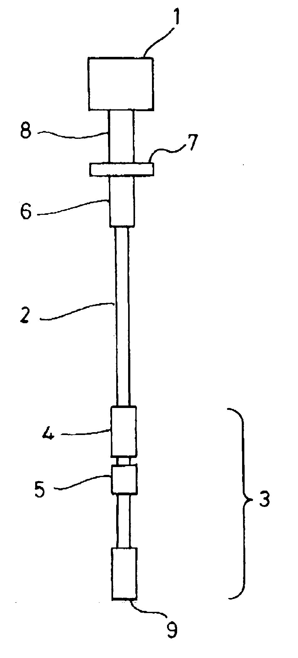
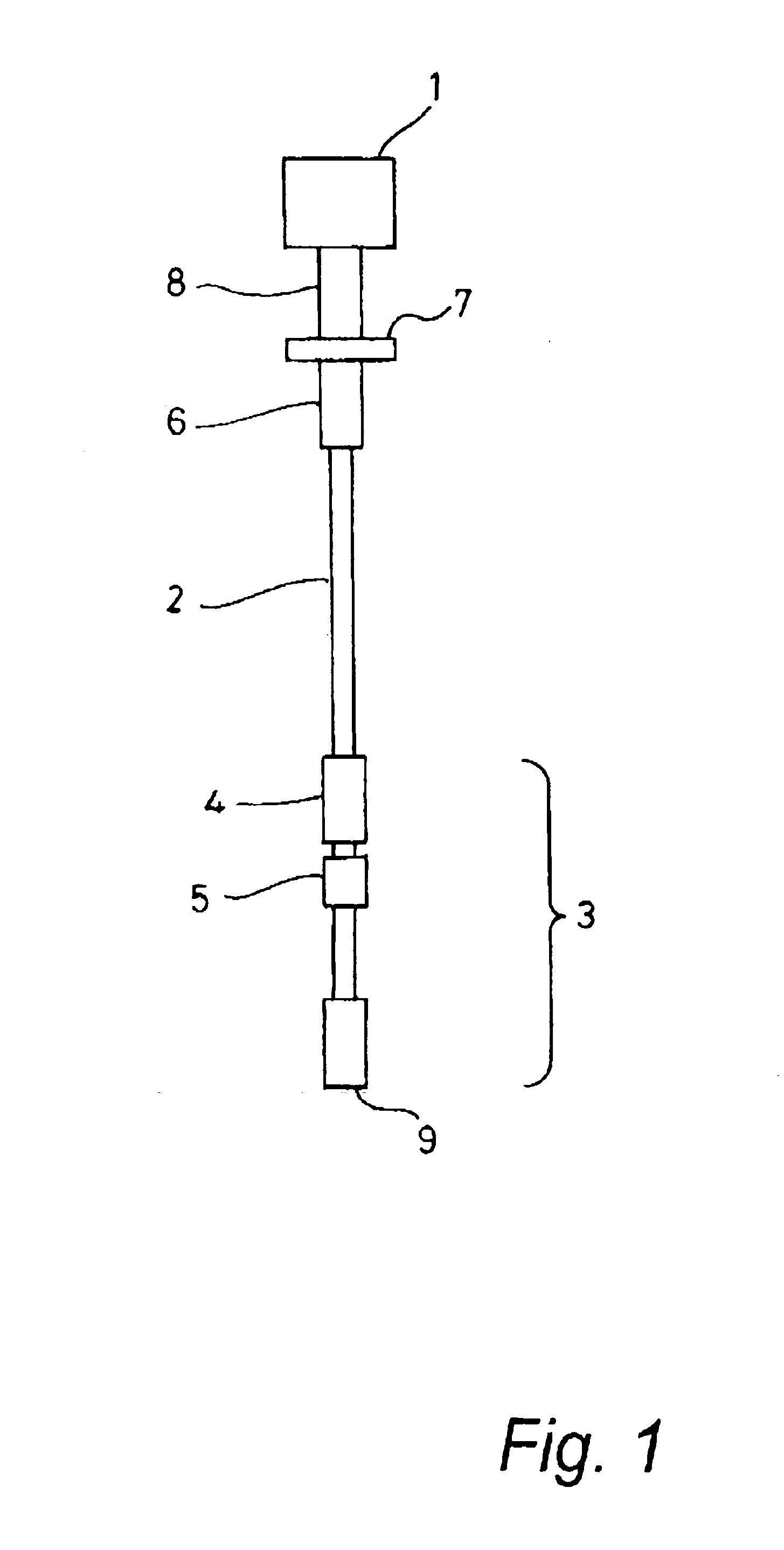
[0040]FIG. 1 shows a schematic a drawing of a telemetry system according to the present invention.

[0041]A surface top drive 1 rotates a drill string 2 and a bottom hole assembly (BHA) 3. A downhole torsional wave actuator (i.e. an acoustic transmitter) 4 is mounted on the drill string near the upper end of the BHA and is acoustically isolated from the rest of the BHA by a baffle 5. At the lower end of the BHA is drill bit 9. Torsional acoustic wave signals propagate up the drill string to be detected at the surface by a measurement sub (i.e. an acoustic receiver) 6.

[0042]Above the measurement sub, a steel reflector 7 terminates the drill string and is connected to the top drive via a linking sub 8. The reflector reflects much of the acoustic noise generated by the top drive and propagated through the linking sub away from the drill string, so that only a relatively small proportion of surface-generated noise enters the drill string. The reflector is able to do this because it has a ...


PUM


Abstract

A drill string telemetry system comprises an acoustic reflector mounted to the surface end of the drill string. The reflector is adapted to reflect surface-generated torsional acoustic noise away from the drill string. The reflector attenuates the power of 500 Hz torsional acoustic noise power impinging on the reflector by a factor of at least 2.

Description

FIELD OF THE INVENTION[0001]The present invention relates to the field of telemetry in hydrocarbon wells. In particular, the invention relates to a drill string telemetry system, an acoustic reflector for such a system, and a method of shielding a drill string telemetry system.BACKGROUND OF THE INVENTION[0002]Communication between down hole sensors and the surface has long been practiced in the hydrocarbon recovery industry. Long-range data signal transmission is, for example, an integral part of techniques such as Measurement-While-Drilling (MWD) and Logging-While-Drilling (LWD). Data signals have been transmitted via various carriers such as electromagnetic radiation transmitted through the ground formation, electrical transmission transmitted through an insulated conductor, pressure pulses propagated through the drilling mud, and acoustic waves propagated through the metal drill string. Each of these methods is associated with varying degrees of signal attenuation and ambient noi...

Claims


Application Information

Patent Timeline
IPC IPC(8): E21B47/16E21B47/12
CPCE21B47/16
Inventor JENKINS, CHARLES RODERICK
Owner SCHLUMBERGER TECH CORP
Why Eureka
Try Eureka