Charge roller of developing device for image forming apparatus

a technology of developing device and charge roller, which is applied in the direction of corona discharge, instruments, applications, etc., can solve the problems of serious environmental pollution, excessive high voltage required for charging the surface of the photosensitive drum, and difficulty in producing an excellent quality charge roller, so as to reduce the size of the charge roller, enhance the quality of printing image, and minimize the durability of the resilient rubber

Inactive Publication Date: 2005-09-13
SAMSUNG ELECTRONICS CO LTD
View PDF12 Cites 12 Cited by
  • Summary
  • Abstract
  • Description
  • Claims
  • Application Information

AI Technical Summary

Benefits of technology

[0035]It is further still another object of the present invention to reduce a size of a charge roller while minimizing durability of a resilient rubber constituting an outer surface of a metal rod.
[0036]It is further still another object of the present invention to prevent an abnormal phenomenon from being occurred at a surface of a photosensitive drum even if a charge roller contacts for a long time period during a stoppage of operation of an image forming apparatus while minimizing a non-crosslinked low molecular polymeric substance existing at a resilient rubber.
[0037]It is still further an object of the present invention to enhance the quality of printing image by allowing an image composition for OA (office automated) machines, such as ink or toner to have metallic gloss revelation capability using organic synthesis metallic material instead of inorganic pigment.

Problems solved by technology

However, it is extremely difficult to produce a charge roller with an excellent quality unless an additional treatment is conducted to a semiconductive resilient rubber since a semiconductive resilient rubber constituting an outer surface of a charge roller has its own volume resistivity of 108 Ωcm or higher.
If a charge roller with a volume resistivity of 108 Ωcm or higher contacts a photosensitive drum, an excessively high voltage is required for charging the surface of the photosensitive drum.
Thus, an amount of ozone generated by the applied high voltage significantly increases, resulting in a serious environmental pollution.
However, many problems arise from those known approaches when applied to practice, as follows.
First, with the above-mentioned method disclosed in U.S. Pat. No. 5,637,395, it is extremely difficult to uniformly disperse an additive like a conductive carbon powder or alkali metal salt onto a semiconductive resilient rubber.
In this case, since the uniformity of the additive applied to the semiconductive resilient rubber is extremely poor, an overall volume resistivity of the semiconductive resilient rubber becomes non-uniform.
Accordingly, an overall surface of a photosensitive drum contacting the semiconductive resilient rubber is non-uniformly charged, resulting in an undesirable image being produced.
In case where an additive is added, the durability of a semiconductive resilient rubber rapidly increases, and it will be difficult to maintain the durability of the semiconductive resilient rubber at 40 or less as prescribed by JISA(Japanese Industrial Standards type AK6301).
Moreover, if a diameter of a charge roller is reduced at such a state, it will be extremely difficult to ensure a uniform contact between the charge roller and the photosensitive drum.
As a result, it will be difficult to reduce the size of the charge roller.
The approaches presented in U.S. Pat. Nos. 5,497,219 and 5,786,091 require a coating process utilizing coating liquid like polyamide, fluoric resin, or epichlorohydrin rubber in addition to a process of forming a semiconductive resilient rubber at an outer periphery of a metal rod, thus significantly deteriorating an overall product process efficiency.
Moreover, the process of coating such liquid makes it difficult to maintain at a low durability of the semiconductive resilient rubber similarly to the case of adding an additive.
This will also make it difficult to reduce a size of a charge roller.
The approach disclosed in U.S. Pat. No. 5,248,560 allows a relatively higher quality charge roller to be produced, it is still problematic from the overall production cost aspect since a high price polyurethane is employed for this approach.
However, it will be extremely difficult to maintain the durability of the outer rubber surface at 10 or less as prescribed by JISA.
Moreover, if a diameter of a charge roller is reduced at such a state, it will be extremely difficult to ensure a uniform contact between the charge roller and the photosensitive drum.
As a result, it will be difficult to reduce the size of the charge roller.

Method used


Image

  • Charge roller of developing device for image forming apparatus
  • Charge roller of developing device for image forming apparatus
  • Charge roller of developing device for image forming apparatus

Examples


Embodiment Construction

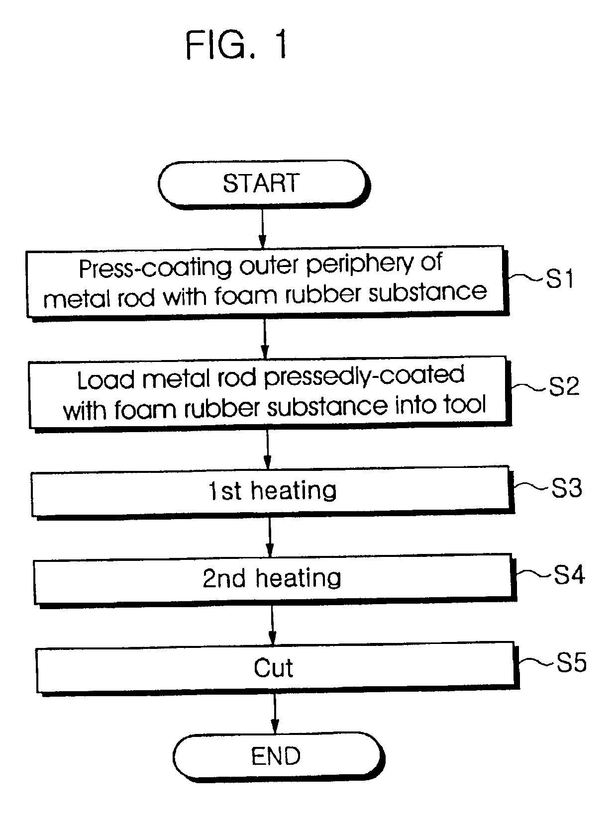
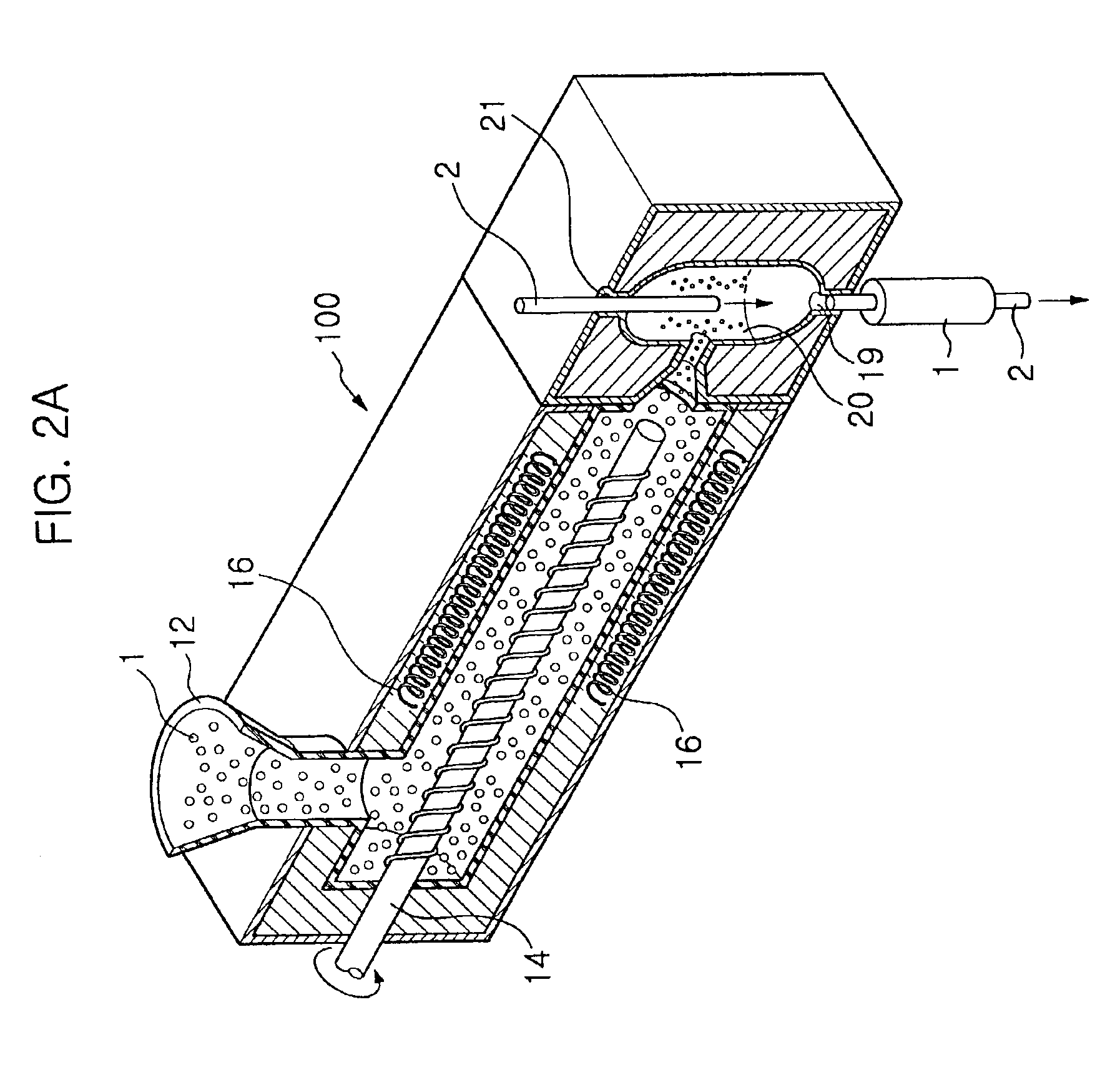
[0056]Referring to FIG. 1, a process of pressedly-coating an outer periphery of a metal rod with a foam rubber substance is performed (S1). In this case, as shown in FIG. 2a, a foam rubber substance 1 at a sheet phase is injected through a foam rubber substance inlet 12 of a compression molding machine 100, and a metal rod 2 having a predetermined diameter is inserted through a metal rod inlet 21.

[0057]Here, the foam rubber substance 1 injected through the inlet 12 is well mixed by a rotation of a mixing shaft 14 and pushed toward a cavity 20. Here, a plurality of heater coils 16 are disposed at a lower portion of the compression molding machine 100. The heater coils 16 serve to heat and melt down the mixed foam rubber substance 1.

[0058]When the metal rod 2 inserted through the metal rod inlet 21 reaches inside of the cavity 20, the melted foam rubber substance 1 pushed toward the cavity 20 is rapidly adhered to an outer periphery of the metal rod 2. Thus, the metal rod 2 extracted ...


PUM

PropertyMeasurementUnit
volume resistivityaaaaaaaaaa
temperatureaaaaaaaaaa

Abstract

A charge roller utilizes a foam rubber substance where epichlorohydrin oxide rubber and an acrylonitrile butadiene rubber are mixed at a ratio of 5:95, or utilizing a crosslinking rubber substance made of epichlorohydrin oxide rubber and acrylonitrile butadiene rubber having a polar low molecular polymeric characteristic, thus allowing the charge roller to maintain a low volume resistivity of 107 Ω cm to 108 Ω cm. As a result, the surface of a photosensitive drum can be charged by a minimum charging voltage, to thereby significantly reduce an amount of ozone. Since a non-crosslinked low molecular polymeric substance existing at a resilient rubber is significantly reduced, the low molecular polymeric substance of the charge roller may not be migrated onto a surface of the photosensitive drum even if the charge roller is in contact with a photosensitive drum for a long time period during a stoppage of operation of an image forming apparatus. As a result, the charge roller may not cause an abnormal phenomenon on the surface of the photosensitive drum.

Description

CROSS-REFERENCE TO RELATED APPLICATIONS[0001]This application is a divisional of Applicant's Ser. No. 09 / 725,089 filed in the U.S. Patent & Trademark Office on 29 Nov. 2000, now U.S. Pat. No. 6,523,263, and assigned to the assignee of the present invention.CLAIM OF PRIORITY[0002]This application makes reference to, incorporates the same herein, and claims all rights accruing thereto under 35 U.S.C. §§119 and 120 through our patent application entitled Charge Roller For A Developing Device Of An Image Forming Apparatus And Method For Fabricating The Same And Tool For Fabricating The Charge Roller earlier filed in the Korean Industrial Property Office on the 29th day of Nov. 1999 and there duly assigned Ser. No. 999 / 53498.BACKGROUND OF THE INVENTION[0003]1. Field of the Invention[0004]The present invention relates to a charge roller of a developer for use of an image forming apparatus adopting an electrophotographic printing system, and more particularly, to a charge roller of a devel...

Claims


Application Information

Patent Timeline
Patent Type & Authority Patents(United States)
IPC IPC(8): G03G15/02B29C44/00G03G15/06B29D99/00C08J9/10C08K3/00C08K3/06C08K5/14C08K5/3492C08L9/02C08L71/03F16C13/00G03G15/08
CPCG03G15/0233Y10T29/49563Y10T29/49798Y10T29/4956Y10T29/49556Y10T29/49547Y10T29/49982G03G15/06
Inventor JO, HAE-SEOGJUNG, HEE-WON
Owner SAMSUNG ELECTRONICS CO LTD
Why Eureka
Try Eureka